
In my extensive experience with industrial gear milling, I have found that the Klingelnberg bevel gear milling machine, particularly the AMK852 model, offers a sophisticated approach to producing high-precision spiral bevel gears. This article draws from my practical insights to delve into the core principles, emphasizing how gear milling processes achieve optimal tooth profiles and contact patterns. I will cover parameter settings, operational mechanics, tooling strategies, and contact zone adjustments, all critical for enhancing gear performance and longevity in applications like heavy machinery.
Starting with parameter setting for bevel gears, I always begin with fundamental design values derived from operational conditions. These include shaft angle, speed ratio, motor RPM, and torque, which directly influence gear geometry. Key parameters such as number of teeth, pitch diameter at the large end, reference cone angle, reference point spiral angle, face width, and modification coefficients must be optimized within the cutter radius and machine capacity. This ensures adequate load-bearing capacity, service life, and safety margins. For instance, the speed ratio in gear milling is defined by the relationship between the gear’s pitch circle radius and the cutter’s rolling circle radius:
$$ \text{speed ratio} = \frac{\text{pitch circle radius of gear}}{\text{rolling circle radius of cutter}} = \frac{\text{number of gear teeth}}{\text{number of cutter blade groups}} $$
This ratio dictates that as the cutter completes one blade group rotation, the gear advances by one tooth pitch. Theoretical parameters, such as normal module and spiral angle at reference points, emerge from the milling results and are inherently tied to the cutter radius. I rely on rolling tests for verification; if contact patterns are suboptimal, adjustments to these parameters become necessary through reprocessing. Below is a summary table of essential parameters in gear milling:
| Parameter Type | Key Variables | Influence on Gear Milling |
|---|---|---|
| Fundamental Design | Shaft angle, speed ratio, torque | Determines gear size, tooth count, and load capacity |
| Geometric | Pitch diameter, cone angle, face width | Affects tooth profile and meshing efficiency |
| Theoretical Output | Normal module, spiral angle | Defined by cutter radius; validated via contact tests |
Moving to the operational principles, gear milling on machines like the AMK852 involves complex relative motions between the workpiece, cutter head, and cradle. I analyze this as a synthesis of differential movements: the workpiece and cutter head rotate to generate involute tooth profiles through continuous indexing, while the cradle’s motion relative to the cutter head produces elongated epicycloidal paths for the tooth length. If the cradle remains stationary, simultaneous slot cutting and indexing occur, with the speed ratio ensuring precise tooth spacing. However, when the cradle rotates with the workpiece, a single rolling pass completes both tooth profile and longitudinal shaping. The absolute and relative velocity centers, such as points \( O_p \) (cradle center) and \( O_o \) (cutter center), dictate the trajectory. For opposite angular velocities \( \omega_p \) and \( \omega_o \), the cutter’s path is an elongated epicycloid:
$$ \rho’ = \frac{\omega_o \rho}{\omega_o – \omega_p} $$
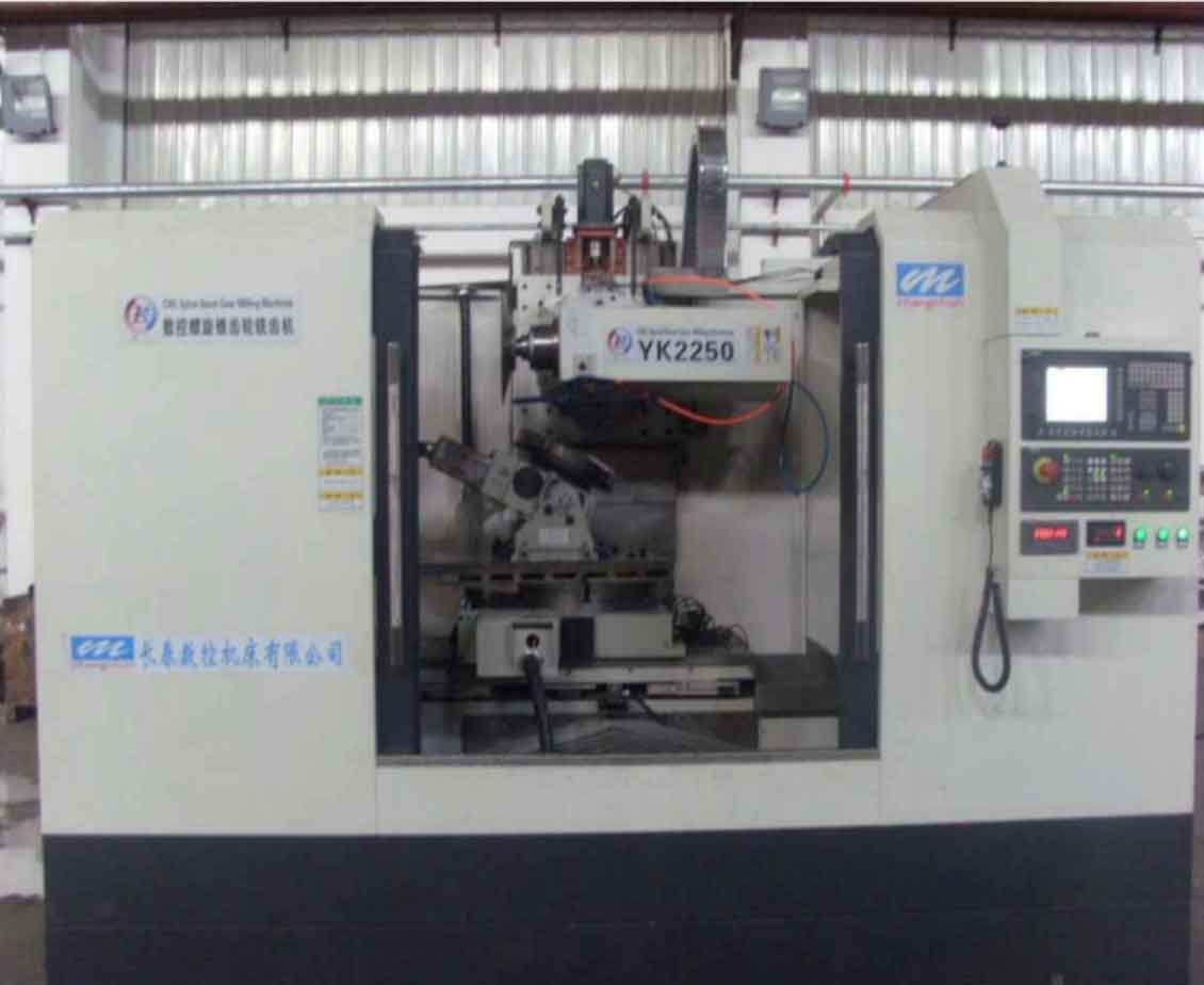
Here, \( \rho \) is the base circle radius, and the motion simulates the cutter rolling purely along this circle. This mechanism is fundamental to gear milling for creating accurate tooth forms. To visualize the setup, consider this image of a modern CNC spiral bevel gear milling machine:
In gear milling tooling, I distinguish between soft cutting for roughing and hard cutting for finishing, each with specific blade configurations. Soft cutting uses a multi-blade setup with 20 blades grouped into five sets (\( Z_o = 5 \)), arranged as inner, inner-middle, outer-middle, and outer blades based on the gear’s helix direction. Middle blades create the slot, while side blades refine the tooth surfaces, with height differentials (e.g., middle blade \( H_a = 1.3M_o \), side blade \( H_a = 1.25M_o \)) allowing for profile modifications. Tooth depth is controlled by blade positioning angles (e.g., \( 240^\circ / Z_o \)), and longitudinal feed is managed via cradle rotation speed. In contrast, hard cutting employs carbide-tipped blades—only inner and outer side blades—for exclusive profile finishing without depth cuts, using 10 blades in five groups. Alignment with a gauge ensures uniform tip height, and the cutter head’s eccentric mechanism introduces crowning to optimize contact patterns. The table below compares these tooling aspects in gear milling:
| Aspect | Soft Cutting | Hard Cutting |
|---|---|---|
| Blade Types | Inner, inner-middle, outer-middle, outer (20 blades) | Inner and outer side blades only (10 blades) |
| Grouping | \( Z_o = 5 \) groups | \( Z_o = 5 \) groups |
| Primary Function | Slot creation and surface roughing | Tooth profile finishing |
| Key Features | Height differential for modifications; helical arrangement | Eccentric mechanism for crowning; gauge alignment |
| Gear Milling Process | Combined roughing and finishing in one cycle | Profile-only generation with variable speeds |
For contact zone rectification, I frequently encounter issues like misaligned or diagonal patterns during gear milling and apply targeted corrections. For instance, if the concave side contact shifts toward the toe or heel on a right-hand helix gear, I adjust the cutter head setting angle \( \Delta m \) by ±1° to 4°. Diagonal patterns require changes to the machine distance setting angle \( \tau \) or \( \Delta m \) on the mating gear, with specific increments based on helix direction. Symmetrical shifts toward the ends can be resolved by combined \( \tau \) and \( \Delta m \) adjustments or paired modifications on both gears. Noise from tooth interference often necessitates tweaks to the root angle \( \delta_E \) or pressure angle via shims (±0.15° to 0.2°). Through gear milling trials, I prioritize methods like altering \( \tau \), \( \Delta m \), or mounting distance for efficiency, as summarized:
| Contact Issue | Correction Method | Typical Adjustment Range |
|---|---|---|
| Concave side shift | Change \( \Delta m \) on cutter head | ±1° to 4° |
| Diagonal pattern | Adjust \( \tau \) or \( \Delta m \) on mating gear | Minutes or degrees as per helix |
| Symmetrical end shift | Combine \( \tau \) and \( \Delta m \) or pair on gears | \( \tau \): minutes; \( \Delta m \): 2° to 4° |
| Interference noise | Modify root angle or pressure angle | \( \delta_E \): +0.15° to 0.2°; shims: ±0.15° |
In conclusion, mastering gear milling on Klingelnberg machines involves harmonizing parameter settings, motion dynamics, tooling strategies, and empirical contact corrections. I emphasize that iterative testing and adjustments, especially to angles and distances, yield the best results for robust spiral bevel gears. This holistic approach not only enhances gear milling efficiency but also ensures reliability in demanding industrial environments.