
Abstract:
This article presents a comprehensive analysis of the Klingelnberg gear milling machine, specifically the AMK852 model, based on theoretical and practical insights. The focus is on understanding the formation of tool paths (long-amplitude trochoid), the role of key machine parameters, and their impact on the adjustment of gear pair contact areas. Through detailed explanations and the use of tables and images, the complexity of gear milling is simplified for better understanding.
1. Introduction
The Klingelnberg gear milling machine, particularly the AMK852 model, is a sophisticated piece of equipment utilized in the manufacturing of spiral bevel gear. These gears are crucial in various industrial applications due to their ability to transmit high torque and power with minimal noise and vibration. This article aims to delve into the working principles of the AMK852, emphasizing the formation of tool paths, machine parameters, and contact area adjustment methods.
2. Setting of Bevel Gear Parameters
2.1 Basic Parameters
The design of spiral bevel gear begins with the establishment of fundamental parameters such as the shaft angle, speed ratio, motor speed, torque, and other operating conditions. Based on these, the number of teeth, large-end pitch diameter, tooth width, cone angle, reference point helix angle, and modification coefficients are set. The design objective is to ensure that spiral bevel gears meet the required load capacity, service life, and safety factors within the limitations of the tool disc radius and machine capabilities.
| Parameter | Description | Impact |
|---|---|---|
| Shaft Angle | Angle between shafts | Affects tooth contact pattern |
| Speed Ratio | Ratio of input to output speeds | Determines gear ratio |
| Motor Speed | Rotational speed of motor | Influences cutting efficiency |
| Torque | Rotational force | Determines load capacity |
| Number of Teeth | Quantity of teeth on gear | Affects pitch diameter and gear ratio |
2.2 Theoretical Parameters
After processing, theoretical parameters such as the reference point, large and small end normal module, and helix angles are obtained. These parameters are determined by the tool disc radius and are verified through roll testing. If the contact area is satisfactory, spiral bevel gear is deemed qualified; otherwise, adjustments are made, which alter the theoretical parameters.
| Theoretical Parameter | Description | Verification Method |
|---|---|---|
| Reference Point | Fixed point on gear | Used for alignment and measurement |
| Normal Module | Module at normal section | Determines tooth size |
| Helix Angle | Angle of tooth helix | Affects tooth engagement |
3. Operating Principle Analysis
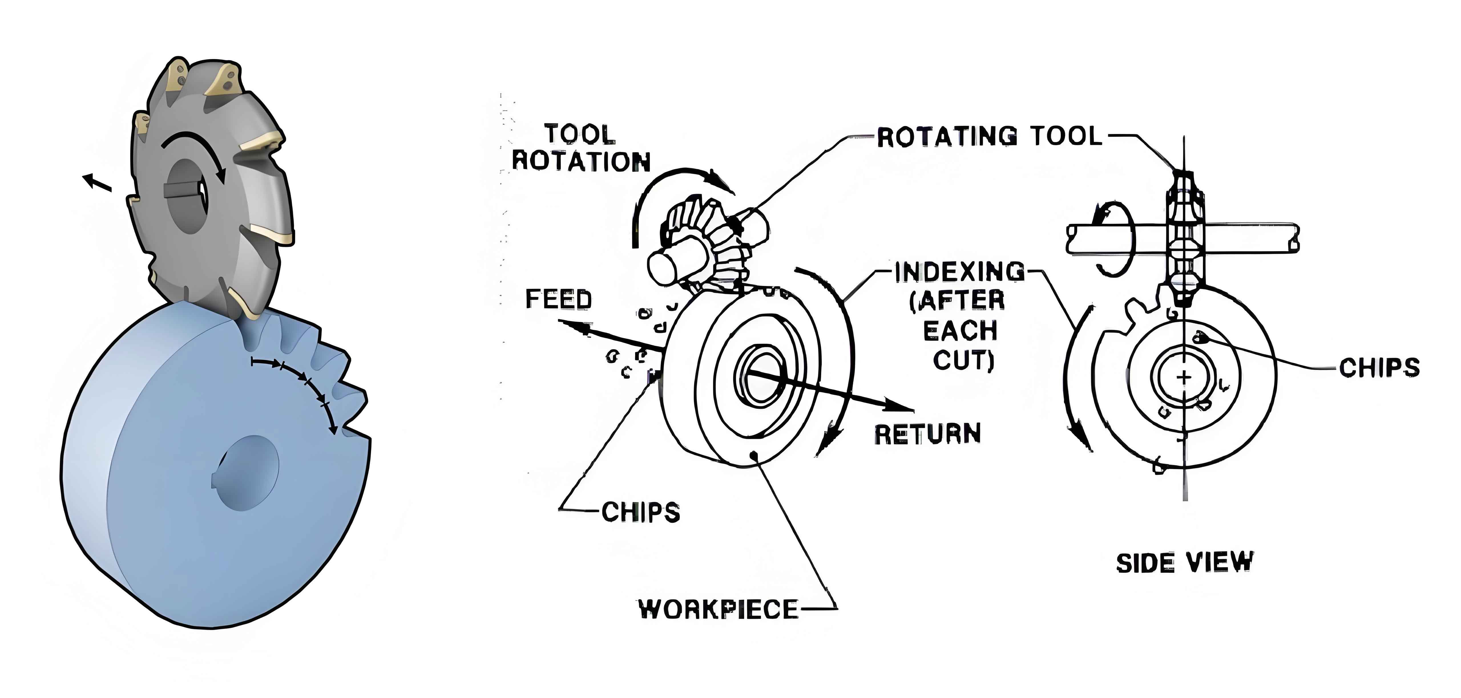
The AMK852 operates through the differential rotation of the workpiece, tool disc, and rocking table. This differential motion generates tooth profiles in the form of normal involute and long-amplitude trochoid. The involute profile is formed by the engagement of the tool edge with the workpiece tooth surface, while the trochoid profile is created by the relative motion between the tool disc and rocking table.
- Involute Profile Formation: Achieved through the differential rotation of the workpiece and tool disc.
- Trochoid Profile Formation: Result of the relative motion between the tool disc and rocking table.
4. Soft and Hard Cutting Tools
4.1 Soft Cutting
Soft cutting tools consist of 20 blades arranged in five groups (ZO=5). These blades are divided into inner, middle, and outer sets, with each set responsible for specific cutting stages. Inner and middle blades initiate the groove, while outer blades refine the tooth surface. Blade positioning and feed rate control are critical for achieving the desired tooth profile.
| Blade Type | Arrangement | Function |
|---|---|---|
| Inner Blade | Closest to center | Initiates groove |
| Middle Blade | Middle position | Continues groove |
| Outer Blade | Furthest from center | Refines tooth surface |
4.2 Hard Cutting
Hard cutting tools are made of carbide inserts and are used for finishing the tooth sides. There are 10 blades arranged in five groups (ZO=5). Tool setting requires the use of a setting gauge to ensure consistent blade heights. Both soft and hard tool discs are two-piece, with inner and outer discs processing convex and concave surfaces, respectively.
| Cutting Stage | Tool Type | Blade Count | Function |
|---|---|---|---|
| Soft Cutting | Inner/Middle/Outer Blades | 20 | Rough and semi-finish cutting |
| Hard Cutting | Carbide Inserts | 10 | Final finish cutting |
5. Adjustment of Contact Areas
Achieving proper contact areas on spiral bevel gears is crucial for optimal performance. Various methods are employed to adjust contact areas, including modifications to the machine setting angle (τ), tool disc setting angle (Δm), and gear installation distance.
5.1 Contact Area Position Adjustment
If the contact area on the concave tooth surface is located at the small or large end, adjusting the tool disc setting angle by ±1° to 4° can center the contact area. If this adjustment is insufficient, further changes may be necessary.
| Contact Area Issue | Adjustment Method | Range |
|---|---|---|
| Concave Tooth Surface | Change Δm | ±1° to 4° |
5.2 Diagonal Contact Area Correction
Diagonal contact areas can be corrected by adjusting either the machine setting angle (τ) on the pinion gear or the tool disc setting angle (Δm) on the mating gear.
| Correction Method | Pinion Gear Adjustment | Mating Gear Adjustment |
|---|---|---|
| Method 1 | Decrease τ | Decrease Δm by 1° to 4° |
| Method 2 | Increase τ | Increase Δm by 1° to 4° |
| Method 3 | Decrease τ | Increase Δm by 1° to 4° |
| Method 4 | Increase τ | Decrease Δm by 1° to 4° |
5.3 Asymmetric Contact Area Adjustment
If the contact area is not centered but symmetric towards the large or small end, adjustments can be made by simultaneously changing both the machine setting angle (τ) and tool disc setting angle (Δm).
| Adjustment Combination | τ Adjustment | Δm Adjustment |
|---|---|---|
| Combination 1 | Increase τ | Decrease Δm by 2° to 4° |
| Combination 2 | Decrease τ | Increase Δm by 2° to 4° |
| Combination 3 | Increase τ | Increase Δm by 2° to 4° |
| Combination 4 | Decrease τ | Decrease Δm by 2° to 4° |
5.4 Interference and Noise Reduction
If interference occurs between tooth tips and roots, causing noise, several adjustments can be made, including:
- Increasing the installation cone angle (δE) by 0.15° to 0.2°
- Adjusting the generation depth (Tw)
- Changing the pinion gear installation distance
- Using wedge-shaped shims to alter the blade pressure angle (±0.15° to ±0.2°)
| Adjustment Method | Description | Impact |
|---|---|---|
| Increase δE | Adjust cone angle | Reduces interference |
| Adjust Tw | Modify generation depth | Adjusts tooth engagement |
| Change Pinion Gear Installation Distance | Alter installation position | Adjusts tooth alignment |
| Use Wedge Shims | Change pressure angle | Adjusts tooth profile |
6. Conclusion
The Klingelnberg AMK852 gear milling machine is a highly sophisticated piece of equipment capable of producing precision spiral bevel gear. Understanding the formation of tool paths, key machine parameters, and methods for adjusting contact areas is crucial for achieving optimal gear performance. Through this comprehensive analysis, we have provided insights into the design, operation, and adjustment of the AMK852, emphasizing the importance of precision and attention to detail in gear milling.