
In the field of mechanical engineering, spiral gears hold a pivotal role as essential components for transmitting motion between intersecting shafts. Their advantages, such as high overlap ratio, strong load-bearing capacity, efficient transmission, smooth operation, and low noise, make them indispensable in automobiles, aircraft, machine tools, and various machinery. However, the precision finishing of hard-toothed surfaces on spiral gears remains a significant challenge, especially in regions where advanced manufacturing technologies are not fully developed. Traditional methods like grinding, lapping, and hard-face milling involve high costs, complexity, or limited applicability. To address this, I explore the application of pulse electrochemical finishing (PECF) as a novel technique for enhancing the surface quality of spiral gears. This article delves into the foundational theories, process parameters, cathode design, and anti-corrosion measures associated with PECF for spiral gears, aiming to provide a comprehensive understanding of its potential in industrial applications.
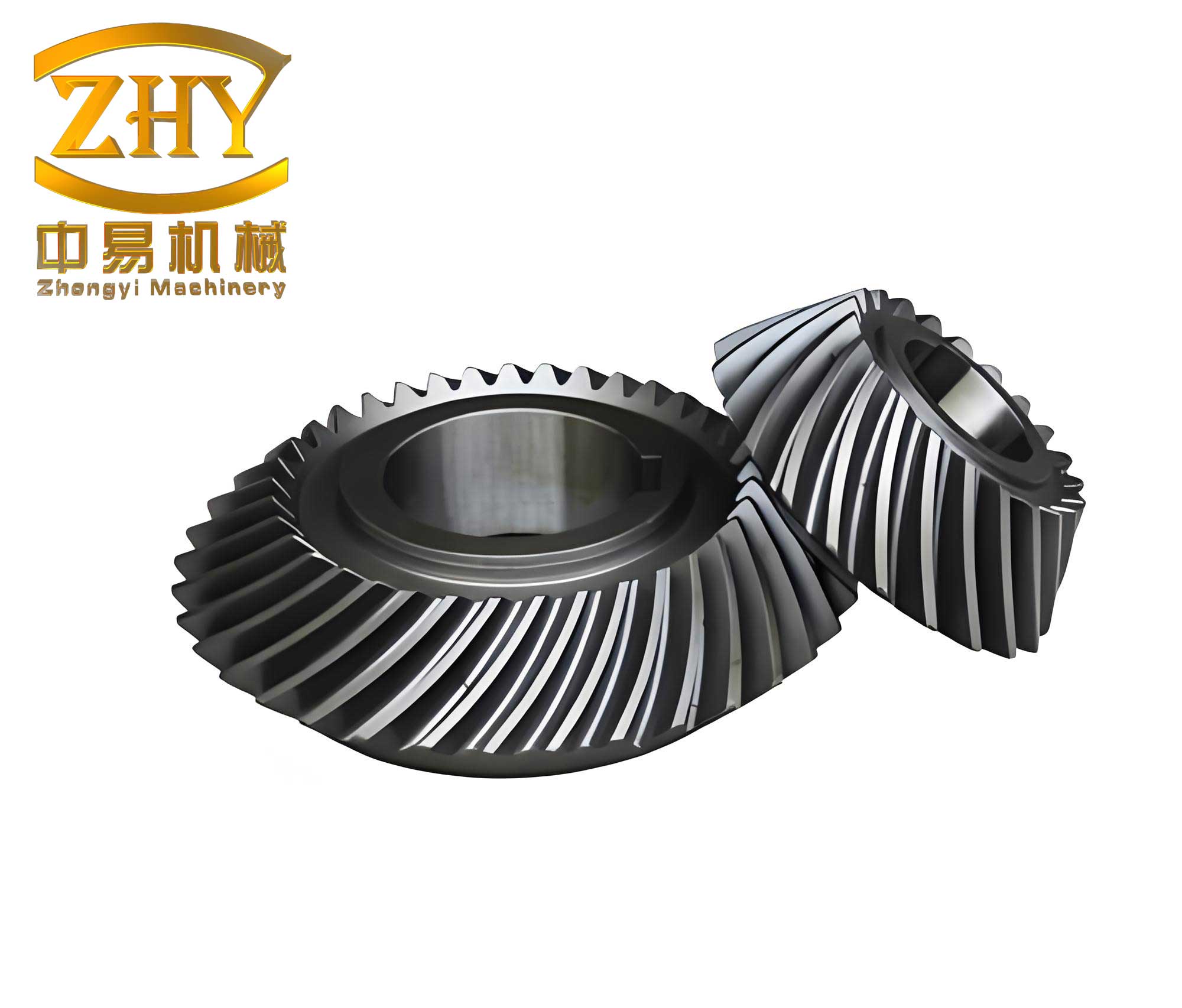
The importance of spiral gears in mechanical systems cannot be overstated. They enable efficient power transmission in complex arrangements, often in heavy-duty applications like automotive differentials and aerospace mechanisms. However, the hard-toothed surfaces of spiral gears, typically hardened to HRC 58-63, require precise finishing to minimize surface roughness and improve longevity. Conventional finishing methods, such as grinding, are accurate but expensive and slow, while lapping offers limited error correction. Hard-face milling, or刮削, has emerged as an alternative, yet it involves high initial investments and specialized equipment. In contrast, pulse electrochemical finishing presents a promising solution due to its ability to rapidly reduce surface roughness without mechanical contact, making it suitable for hard materials. This technique leverages electrochemical anode dissolution under pulsed current, which enhances control over the process and improves surface integrity. In this article, I will discuss the fundamental aspects of PECF, focusing on its application to spiral gears, and provide insights into optimizing the process for industrial adoption.
Pulse electrochemical finishing operates on the principle of electrochemical anode dissolution, where the workpiece serves as the anode and a tool as the cathode in an electrolyte solution. When a pulsed current is applied, metal ions are removed from the anode surface, leading to smoothing and brightening. The basic reaction at the anode involves oxidation: $$ M \rightarrow M^{n+} + n e^- $$ where \( M \) represents the metal, \( M^{n+} \) are dissolved ions, and \( n e^- \) are electrons released. At the cathode, reduction occurs: $$ 2H_2O + 2 e^- \rightarrow H_2 \uparrow + 2OH^- $$ producing hydrogen gas. The volume of metal removed, \( V \), follows Faraday’s law: $$ V = \eta \omega I t $$ where \( \eta \) is current efficiency, \( \omega \) is the volumetric electrochemical equivalent, \( I \) is current, and \( t \) is time. For surface finishing, the key is to achieve uniform dissolution, which is influenced by factors like current density, electrolyte composition, and pulse parameters. PECF offers advantages over direct current electrochemical machining, including better flow field management, reduced heat accumulation, and enhanced precision due to the pulsating nature of the current.
The smoothing mechanism in PECF can be divided into macro-leveling and micro-leveling (or brightening). Macro-leveling occurs due to non-uniform current distribution on rough surfaces. Peaks on the workpiece are closer to the cathode, resulting in higher current density and faster dissolution compared to valleys. This effect, known as the “tip effect,” gradually reduces surface roughness. Mathematically, the removal rate \( V_a \) can be expressed as: $$ V_a = \eta \omega K \frac{U_R}{\Delta} $$ where \( K \) is electrolyte conductivity, \( U_R \) is the ohmic voltage drop, and \( \Delta \) is the inter-electrode gap. Over time, the gap increases, and the removal rate decreases, leading to leveling. The relationship between removal depth \( \Delta h \) and initial gap \( y_0 \) is given by: $$ \Delta h = \sqrt{2 \eta \omega K U_R t + y_0^2} – y_0 $$ This shows that smaller initial gaps yield faster leveling, but excessively small gaps may cause issues like sparking or poor electrolyte flow.
Micro-leveling, on the other hand, is a surface kinetics phenomenon related to the formation of a salt film on the anode. Under high current densities, a limiting current is reached where a passive layer forms, leading to bright surfaces. This occurs when the pulse current density exceeds a threshold, promoting uniform dissolution at the atomic level. The transition to brightening depends on factors like electrolyte composition and pulse width. For instance, in neutral salt solutions like NaNO₃, the anode potential must be high enough to enter the transpassive region for effective brightening. Pulse parameters, such as frequency and duty cycle, play a crucial role in controlling this process. By optimizing these parameters, PECF can achieve mirror-like finishes on spiral gears, significantly enhancing their surface quality.
To understand the practical implications, I conducted experimental studies on various process parameters affecting PECF quality. The key parameters include current density, electrolyte composition, workpiece material, inter-electrode gap, pulse frequency, and pulse width. Below is a summary table of their effects based on experimental data:
| Parameter | Effect on Surface Roughness | Optimal Range for Spiral Gears |
|---|---|---|
| Current Density | Higher density reduces roughness up to a limit; excessive density causes uneven dissolution. | 30–60 A/cm² |
| Electrolyte Composition | NaNO₃ solutions (15–20%) offer good leveling; NaClO₃ provides better precision but higher cost. | NaNO₃ at 20% concentration |
| Workpiece Material | Low-carbon steels (e.g., 20CrMnTi) yield better results; high-carbon materials may leave insoluble carbides. | Steel with carbon content below 0.3% |
| Inter-electrode Gap | Smaller gaps (0.2–0.3 mm) enhance leveling; gaps above 0.6 mm reduce effectiveness. | 0.2–0.4 mm |
| Pulse Frequency | Higher frequencies improve surface finish; saturation occurs around 10 kHz. | 1–10 kHz |
| Pulse Width | Narrow pulses (e.g., 10–50 µs) with adequate off-time enhance precision and reduce heat. | On-time: 10–50 µs; Off-time: 20–100 µs |
Current density is a dominant factor in PECF. In experiments with spiral gear materials like 20CrMnTi, increasing current density from 10 to 50 A/cm² reduced surface roughness \( R_a \) from approximately 3.2 µm to 0.4 µm. However, beyond 60 A/cm², roughness increased due to non-uniform dissolution and possible sparking. The relationship can be modeled as: $$ R_a = a \cdot i^{-b} $$ where \( i \) is current density, and \( a \) and \( b \) are constants derived from experimental data. For spiral gears, maintaining an optimal current density ensures efficient material removal without compromising surface integrity.
Electrolyte composition significantly influences the finishing outcome. Neutral salts like NaNO₃ are preferred for their balanced properties, providing moderate leveling and brightening. The polarization curve for iron in NaNO₃ shows a clear passive region, which helps control dissolution. The conductivity \( \kappa \) of the electrolyte affects the removal rate, as seen in the equation: $$ V_a = \eta \omega \kappa \frac{U_R}{\Delta} $$ For a 20% NaNO₃ solution, \( \kappa \) is approximately 0.133 S/cm, which offers a good balance between speed and precision. Additives, such as anti-corrosion agents, can be included without severely impacting conductivity, as discussed later.
Workpiece material plays a role in surface quality after PECF. Spiral gears made of low-alloy steels like 20CrMnTi respond well, with smooth surfaces achieved. High-carbon steels or cast iron may exhibit pitting or residual carbides, as Fe₃C phases are not easily dissolved electrochemically. This highlights the need for material selection or pre-treatment when processing spiral gears with varied compositions.
The inter-electrode gap is critical for precision. Small gaps enhance the tip effect, accelerating leveling. However, gaps below 0.2 mm can lead to clogging or short circuits. For spiral gears, a gap of 0.3 mm is often optimal, allowing sufficient electrolyte flow while maintaining high current density. The relationship between gap \( \Delta \) and removal depth \( \Delta h \) over time \( t \) is: $$ \Delta = \sqrt{2 \eta \omega K U_R t + \Delta_0^2} $$ where \( \Delta_0 \) is the initial gap. This nonlinear behavior necessitates careful control during finishing of complex spiral gear surfaces.
Pulse frequency and width affect the dynamics of PECF. Higher frequencies promote pressure waves in the electrolyte, improving mass transfer and reducing stagnation. Experimentally, increasing frequency from 1 kHz to 10 kHz reduced \( R_a \) from 0.8 µm to 0.2 µm for spiral gear samples. Pulse width controls the duration of dissolution; shorter on-times with longer off-times help dissipate heat and refresh the electrolyte. The duty cycle, defined as the ratio of on-time to total pulse period, should be optimized—for example, a 1:2 ratio (on-time:off-time) works well for spiral gears. The mathematical representation of pulse effects involves the average current density \( i_{avg} \): $$ i_{avg} = i_{peak} \cdot \frac{t_{on}}{t_{on} + t_{off}} $$ where \( i_{peak} \) is the peak current density. Adjusting these parameters allows fine-tuning of the finishing process for spiral gears.
Another crucial aspect is the influence of cathode surface micro-topography on finishing quality. In PECF, the cathode’s surface roughness can be replicated onto the workpiece through a phenomenon called “error replication,” which counteracts the leveling effect. This occurs when non-uniform gaps exist due to cathode imperfections. The error replication value \( \lambda \) can be estimated as: $$ \lambda = C \cdot t \left( \frac{1}{\Delta} – \frac{1}{\Delta + \delta} \right) $$ where \( C = \eta \omega K U_R \), \( \delta \) is the cathode surface roughness, and \( t \) is time. For small gaps (e.g., \( \Delta < 0.3 \) mm), a rough cathode (e.g., \( \delta > 1 \) µm) can significantly degrade the finish. However, for gaps above 0.6 mm, the tip effect dominates, minimizing replication. Experiments with spiral gear cathodes showed that when cathode roughness \( R_a \) is below 0.2 µm, its impact on workpiece roughness is negligible. Additionally, moving the cathode relative to the workpiece at speeds above 20 mm/s further reduces replication. Therefore, for spiral gear PECF, using cathodes with smooth surfaces (\( R_a < 0.2 \) µm) and maintaining moderate gaps is advisable to achieve high-quality finishes.
The design of cathodes for spiral gear PECF is a complex task, requiring adaptation to gear geometry and machining principles. Spiral gears are typically produced by methods like single-cycle (non-generated) or generating (rolling) processes. In single-cycle methods, used for large gears, the tool replicates a straight-line tooth profile, while generating methods, used for small gears, create curved profiles through relative motion. To apply PECF, I propose simulating these processes by replacing cutting tools with cathodes. For example, in a modified Gleason No. 16 gear milling machine, cathodes are mounted on a tool holder that mimics the motion of a cutting tool. The cathode design must ensure uniform electrolyte flow and consistent gaps along the spiral gear tooth flanks. A key consideration is the number of cathodes; reducing the count from traditional tool sets (e.g., 30 blades) to 14 or fewer can simplify design while maintaining effectiveness, provided the rotational speed is adjusted. The “ridge width” \( f \) on generated gears, which affects surface smoothness, is given by: $$ f = \frac{2\pi A \omega_c \sin \psi \cos \alpha_0}{n V \cos \phi} $$ where \( A \) is the mean cone distance, \( \omega_c \) is the cradle speed, \( \psi \) is the spiral angle, \( \alpha_0 \) is the pressure angle, \( n \) is the number of blade sides, \( V \) is the cutting speed, and \( \phi \) is the gear angle. By increasing \( n \) or \( V \), \( f \) can be minimized, reducing surface irregularities. For PECF, cathode parameters should be chosen to make the effective ridge width smaller than that from cutting, ensuring overlapping dissolution for smoother spiral gear surfaces.
Cathode structures often combine metal and insulating materials to facilitate electrolyte supply and electrical insulation. For instance, a cathode for internal cutting of spiral gears might include copper tubes for current conduction and electrolyte channels, embedded in an epoxy resin holder. The flow field design is critical to avoid dead zones or air pockets; experiments show that side-entry electrolyte injection improves uniformity. Below is a table summarizing cathode design considerations for spiral gear PECF:
| Design Aspect | Requirement | Solution for Spiral Gears |
|---|---|---|
| Electrolyte Flow | Uniform distribution across tooth surface | Side-injection channels with pressures of 0.2–0.5 MPa |
| Gap Control | Consistent 0.2–0.4 mm gap along profile | Precision adjustment via machine settings and shims |
| Cathode Material | Conductive, corrosion-resistant, and smooth | Stainless steel or copper with epoxy insulation |
| Number of Cathodes | Balanced coverage and simplicity | 10–14 cathodes per side, depending on gear size |
| Insulation | Prevent short circuits and machine corrosion | Insulating tool holders and sealed connections |
In practical tests on spiral gears, PECF reduced surface roughness from an initial \( R_a \) of 3–5 µm to below 0.5 µm within minutes, demonstrating its efficiency. However, challenges remain, such as sensitivity to heat treatment distortions in spiral gears, which can cause uneven gaps and sparking. Future work could involve adaptive control systems to dynamically adjust parameters during finishing.
Corrosion of machine tools and workpieces is a significant concern in PECF due to prolonged exposure to electrolytes. Spiral gear machining centers, like the Gleason No. 16, have complex structures where components like fixtures and spindles may contact the electrolyte. To address this, I investigated anti-corrosion additives for NaNO₃ electrolytes. Two types were tested: an alkaline-based additive B₁ and a salt-based additive B₂. Experiments involved immersing Q235 steel samples in 20% NaNO₃ solutions with varying additive concentrations and monitoring corrosion over time. The results indicated that B₂ at 2% concentration provided adequate corrosion protection without severely affecting electrolyte conductivity. Conductivity measurements showed that adding B₂ reduced current flow by less than 10% at 20 V, whereas B₁ caused more significant drops. The volt-ampere characteristics can be expressed as: $$ I = \kappa A \frac{U}{\Delta} $$ where \( I \) is current, \( \kappa \) is conductivity, \( A \) is area, \( U \) is voltage, and \( \Delta \) is gap. With B₂, \( \kappa \) remained above 0.12 S/cm, suitable for PECF of spiral gears. Thus, incorporating 2% B₂ into the electrolyte is recommended to protect machinery while maintaining process efficiency.
In conclusion, pulse electrochemical finishing offers a viable method for enhancing the surface quality of spiral gears, particularly hard-toothed surfaces. Through theoretical analysis and experimental studies, I have outlined the fundamentals of PECF, including its macro- and micro-leveling mechanisms, the influence of key parameters like current density and gap, and the importance of cathode design and anti-corrosion measures. For spiral gears, optimal parameters include a current density of 40–50 A/cm², a 20% NaNO₃ electrolyte with 2% salt-based anti-corrosion additive, a gap of 0.3 mm, and pulse frequencies around 5–10 kHz. Cathodes should have smooth surfaces (\( R_a < 0.2 \) µm) and be designed to mimic gear-cutting motions, with attention to flow field uniformity. Future advancements may involve CNC-integrated PECF systems for spiral gears, allowing real-time adjustments and combining electrochemical with mechanical actions for even better finishes. By adopting PECF, manufacturers can potentially reduce costs, improve gear longevity, and lower noise in applications involving spiral gears, contributing to overall mechanical system performance. The continuous evolution of this technology holds promise for broader industrial adoption, making spiral gears more reliable and efficient in demanding environments.