
The traditional spiral bevel gear machining is based on the principle of “imaginary flat top gear”. At present, the basic concept of spiral bevel gear machining methods at home and abroad is also the principle of “hypothetical flat top gear”, which is only continuously improved and modified on the basis of this principle. As shown in Figure 1, imagine a flat top gear meshing with the gear to be processed. The hypothetical flat top gear is a bevel gear with a top cone angle of 90 degrees and a pure rolling relationship between the pitch cone and the pitch cone of the gear to be processed. In the process of gear cutting, the hypothetical flat top gear will carry out meshing transmission without clearance with the gear to be processed. The movement track of the cutter teeth on the milling cutter head in the machining process is the tooth surface of the flat top gear, so the cutter teeth are cut on the gear blank according to the meshing transmission relationship between the flat top gear and the gear to be machined to generate the tooth surface of spiral bevel gear.

In the process of gear cutting, because the imaginary flat top gear and the gear to be processed are conjugate transmission relationship, the pitch cone surface of the imaginary gear and the pitch cone surface of the gear to be processed must ensure the pure rolling relationship; The tooth groove of the root cone of the gear to be machined is cut by the tooth top plane of the imaginary gear in the transmission process, so the tooth top rotation plane of the imaginary gear must be tangent to the root cone of the gear to be machined. Then the rotation axis of the gear to be processed forms an angle with the rotation axis of the imaginary flat top gear, which is the axis intersection angle of “90 ° + root cone angle”. In order to ensure the above relationship, the tooth profile angle of the blade must be corrected. At the same time, due to the unequal pressure angle of the teeth in the tooth height direction, the gear cutting machine tool needs to be adjusted.
Combined with the cutting principle of spiral bevel gear, the key structure of traditional spiral bevel gear cutting machine tool is analyzed. As shown in Figure 2, the motion of the milling cutter head is jointly controlled by the shaking table drum, eccentric and cutter tilting mechanism, so that the spatial motion track of the cutter teeth in the machining process is the tooth surface of the imaginary flat top gear, so as to ensure the pure rolling relationship with the bevel gear to be machined, and cut the tooth surface of the spiral bevel gear.
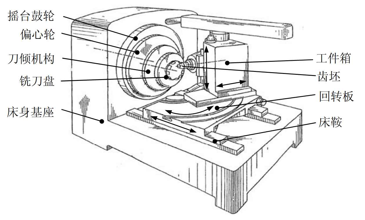
For the processing of spiral bevel gears with different rotation directions, it is mainly determined by adjusting the relative position of the bevel gear to be processed and the rotation axis of the shaking table in the vertical Z direction. The gear blank spindle can move up and down along the vertical track on the side of the workpiece box to adjust the vertical wheel position. When the axis of the gear blank spindle intersects with the axis of the shaking table, the scale value of the vertical wheel position is 0. When machining left-hand spiral bevel gear, the gear blank spindle should move downward relative to the shaking table axis, and the vertical gear position scale value is negative; The opposite is true when machining right-hand spiral bevel gears. For the correction of bevel gear tooth thickness and cutting depth, it can be adjusted by controlling the movement of the workpiece box with the rotary plate in the horizontal direction. When the workpiece box moves forward, the tooth thickness of the processed spiral bevel gear becomes smaller and the tooth depth becomes larger; On the contrary, the tooth thickness becomes larger and the tooth depth becomes smaller. The adjustment of the installation angle of the gear to be processed can be adjusted by controlling the rotation of the workpiece box on the rotary plate. The initial machining position must ensure that the axis intersection angle between the axis line of the gear blank and the axis of the shaking table of the machine tool is “90 ° + root cone angle”. In the process of gear cutting, the feed and retract movement is realized by controlling the rotary movement of the workpiece box on the rotary plate and its forward and backward movement with the rotary plate on the bed saddle.