
Understanding spur gear geometry and calculations is essential for designing and specifying spur gears accurately. Here are the key aspects of spur gear design and the calculations involved:
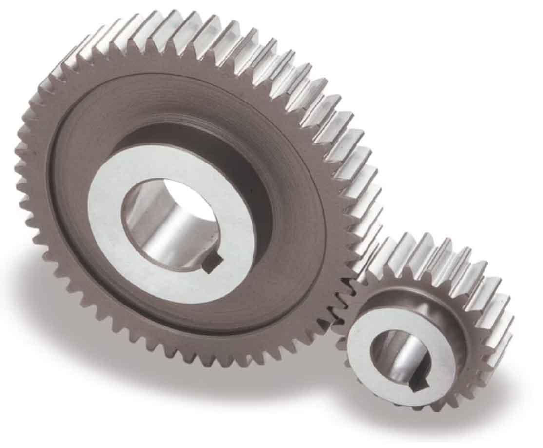
1. Gear Terminology:
- Pitch Circle: The imaginary circle that passes through the center of the gear and represents the effective point of contact between two meshing gears.
- Pitch Diameter (D): The diameter of the pitch circle.
- Module (M): The ratio of the pitch circle diameter to the number of teeth. It determines the size of the gear teeth and is typically measured in millimeters.
- Number of Teeth (N): The total count of teeth on a gear.
- Pressure Angle (θ): The angle between the line perpendicular to the tooth profile and the tangent to the pitch circle. Common pressure angles are 14.5°, 20°, and 25°.
2. Calculation of Basic Parameters:
- Diametral Pitch (P): The number of teeth per inch of the pitch diameter. It is calculated as the reciprocal of the module (P = 1/M).
- Circular Pitch (PC): The distance between corresponding points on adjacent teeth along the pitch circle. It is calculated as the pitch circumference divided by the number of teeth (PC = πD/N).
- Tooth Thickness (T): The width of an individual tooth measured along the pitch circle. It is calculated as the circular pitch divided by two (T = PC/2).
- Addendum (a): The radial distance from the pitch circle to the top of the tooth.
- Dedendum (b): The radial distance from the pitch circle to the bottom of the tooth.
- Whole Depth (h): The sum of the addendum and the dedendum (h = a + b).
3. Contact Ratio and Interference:
- Contact Ratio: The ratio of the length of the path of contact to the circular pitch. A higher contact ratio ensures smoother and more uniform tooth engagement.
- Interference: Interference occurs when the tooth tip of one gear interferes with the root of the mating gear. It is important to avoid interference to ensure proper gear operation.
4. Gear Ratio:
- Gear Ratio (R): The ratio of the number of teeth on the driving gear (N1) to the number of teeth on the driven gear (N2). It determines the speed and torque relationship between the driving and driven gears.
5. Tooth Profile:
- Involute Profile: The tooth profile of spur gears is typically involute, which means the tooth profile is generated by the rolling of a string unwound from a base circle on the pitch circle.
These calculations provide the fundamental parameters required for spur gear design. They enable engineers to determine the appropriate gear size, tooth geometry, and other specifications based on the desired gear ratio, speed, torque, and application requirements.
It’s important to note that there are additional factors and considerations for gear design, such as tooth strength calculations, material selection, tooth surface finish, and lubrication. Complex gear design software and standards exist to assist in detailed gear design.
By understanding the basic geometry and calculations involved in spur gear design, engineers can effectively design and specify spur gears that meet the desired performance, load capacity, and reliability requirements in various applications.