
Chapter 1: The Machining Process of Gear Grinding
Gear grinding is a precision machining method used to create accurate and smooth gear tooth profiles. It’s commonly employed when high precision and surface quality are required for gears used in various applications, such as automotive transmissions, industrial machinery, and more. The process you’ve outlined can be further detailed as follows:
- Clamping Workpiece: Properly securing the workpiece on the gear grinding machine’s workbench is essential. This ensures that the gear is positioned accurately and securely for the grinding operation. Any misalignment or incorrect positioning can lead to inaccuracies in the final gear profile.
- Selection of Grinding Tools: The choice of grinding tools is crucial for achieving the desired gear profile. The grinding wheel is the primary tool used in gear grinding. These wheels have abrasive particles embedded in a matrix, and they remove material from the workpiece through abrasive action. The selection of the grinding wheel depends on factors like the type of gear (spur, helical, bevel, etc.), material of the gear, desired accuracy, and surface finish.
- Set Process Parameters: Setting the appropriate process parameters is a critical step in achieving the desired gear quality. Parameters include:
- Grinding Depth: This refers to the amount of material to be removed during each pass of the grinding wheel. It directly affects the rate at which the gear tooth profile is formed.
- Grinding Speed: The rotational speed of the grinding wheel. It affects the cutting action and heat generation during grinding.
- Feed Speed: The rate at which the workpiece and grinding wheel come into contact. It determines how quickly material is removed and impacts surface finish.
- Dressing Frequency: Over time, the grinding wheel can become dull due to wear. Dressing involves removing dull abrasive grains to expose fresh cutting edges, maintaining consistent cutting performance.
- Coolant/Lubrication: Gear grinding generates heat, which can affect the integrity of the gear and the grinding wheel. Coolant or lubrication helps dissipate heat and prevents damage.
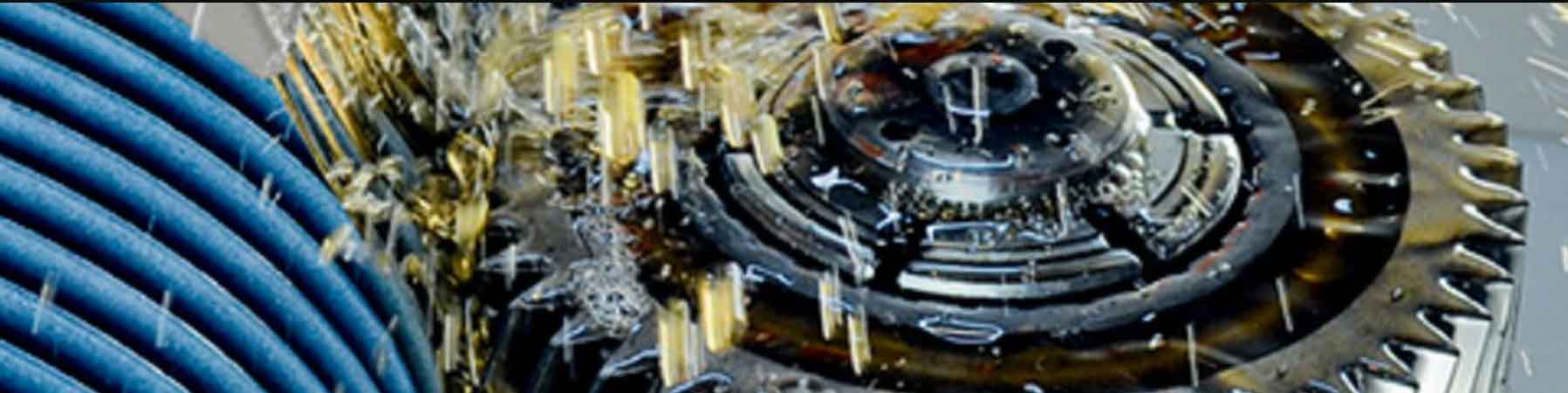
- Grinding Operation: The grinding wheel and the gear workpiece come into contact, and the grinding wheel removes material from the workpiece to shape the gear teeth. The gear grinding machine controls various parameters, including the rotation of the grinding wheel, the rotation of the workpiece, the depth of cut, and the feed rate. These parameters are precisely controlled to ensure accurate gear tooth profiles and surface finishes.
Gear grinding is a complex process that requires skilled operators, advanced machinery, and a deep understanding of gear geometry and machining principles. It’s often used for producing high-precision gears that meet stringent quality requirements in terms of accuracy, noise reduction, and durability.
Chapter 2: The Advantages of Gear Grinding
Summarized the advantages of gear grinding quite accurately. Here’s a more detailed explanation of each advantage:
- High Precision: Gear grinding is a precision machining process that can achieve extremely accurate gear tooth profiles and dimensions. This is crucial for gears used in applications where precise meshing and transmission of power are essential. The controlled removal of material during grinding ensures that the final gear dimensions closely match the intended specifications.
- Good Surface Quality: Gear grinding produces a smooth and consistent surface finish on gear teeth. The abrasive nature of the grinding process helps remove any imperfections, resulting in a refined surface that reduces friction and wear during gear operation. The improved surface quality also contributes to better lubrication retention, leading to increased gear lifespan.
- Low Noise and Vibration: The high precision and improved surface quality achieved through gear grinding contribute to quieter and smoother gear operation. When gears are accurately shaped and finished, they mesh more smoothly, reducing the likelihood of noise and vibration generation during operation. This is particularly important in applications where noise reduction is a priority, such as automotive transmissions.
- Wide Application Range: Gear grinding technology is versatile and can be applied to various types of gears, including helical gears, spur gears, bevel gears, and more. This adaptability makes gear grinding suitable for a wide range of industries and applications, from automotive and aerospace to industrial machinery.
- Consistency and Repeatability: Gear grinding is a controlled process that can be precisely replicated across multiple workpieces. This consistency is crucial for producing gears that match specified tolerances and requirements. It ensures that each gear produced using the grinding process meets the same high-quality standards.
- Material Removal Control: Gear grinding allows for precise control over the amount of material removed from gear teeth. This level of control is beneficial when working with materials that have strict limitations on heat generation or when optimizing gear geometry for specific applications.
- Improved Gear Strength: The controlled nature of the grinding process can result in improved gear tooth strength due to the careful removal of material. This can lead to gears that have enhanced resistance to fatigue and other stress-related failures.
- Reduced Need for Secondary Operations: Gear grinding often produces gears with such high precision and surface quality that additional finishing operations, such as polishing, honing, or lapping, may be unnecessary. This can streamline the manufacturing process and reduce production time and costs.
Gear grinding technology offers a range of advantages that make it a preferred choice for manufacturing high-quality gears with precision, durability, and optimal performance characteristics.
Chapter 3: The Method of Gear Grinding
The two main methods used in gear grinding: continuous generation grinding and form grinding (sometimes referred to as chip grinding or slice grinding). Here’s a bit more detail about each method:
- Continuous Generation Grinding: In continuous generation grinding, both the gear workpiece and the grinding wheel are in constant relative motion. The grinding wheel has a profile that is the negative of the gear tooth profile. As the workpiece and the grinding wheel mesh together, the motion between them generates the desired gear tooth profile on the workpiece. This method is highly productive and efficient for mass production of gears, especially when identical profiles need to be created on multiple workpieces.However, continuous generation grinding requires precise control of various parameters, including the speed and feed rates of the grinding wheel, the depth of cut, and the relative positioning of the workpiece and the grinding wheel. Achieving the correct profile requires tight control over these parameters.
- Form Grinding (Chip Grinding or Slice Grinding): Form grinding, also known as chip grinding or slice grinding, involves using a grinding wheel with a profile that corresponds to the desired shape of the gear tooth. Unlike continuous generation grinding, where the grinding wheel generates the profile during motion, in form grinding, the wheel’s shape itself determines the profile of the gear tooth.The workpiece and the grinding wheel are set in relative motion, and as the wheel contacts the workpiece, it grinds away material to match its profile. This method is particularly suited for one-off or small batch production since it allows for more flexibility in achieving various gear profiles without having to change the grinding wheel as frequently.However, as you mentioned, one drawback of form grinding is that the grinding wheel needs to be replaced or dressed more often to maintain the desired profile. This can lead to increased downtime and tooling costs compared to continuous generation grinding.
Both methods have their strengths and weaknesses, and the choice between them depends on factors such as the production volume, the required precision, the complexity of gear profiles, and the available equipment.
Chapter 4: Precision and Error Control of Gear Grinding
Achieving high-precision gear tooth profiles through gear grinding involves careful control of various parameters and addressing potential sources of error. Let’s delve deeper into the key points you’ve mentioned:
- Grinding Parameters Control:
- Grinding Depth: This refers to how much material is removed during each grinding pass. It’s important to control this parameter precisely to achieve the desired tooth profile and maintain consistency across all teeth.
- Feed Rate: The feed rate determines how fast the grinding wheel moves across the gear tooth surface. A consistent feed rate is necessary to avoid variations in tooth geometry.
- Grinding Speed: The rotational speed of the grinding wheel affects the cutting action. Higher speeds can lead to better cutting efficiency, but they must be balanced with the risk of thermal damage and wear on the wheel.
- Tool Wear and Deformation:
- Grinding Wheel Wear: As the grinding wheel interacts with the gear teeth, it gradually wears down. This wear can lead to changes in the shape of the wheel, affecting the accuracy of the ground teeth. Regular monitoring and dressing of the wheel are important to maintain its shape.
- Thermal Effects: Grinding generates heat, which can lead to thermal expansion of the workpiece and the grinding wheel. This expansion can impact the precision of the ground teeth. Using coolants and controlling the grinding process parameters can help mitigate thermal effects.
- Tool Deformation: The grinding wheel itself can undergo deformation due to the forces and pressures involved in the grinding process. This can lead to inaccuracies in the ground tooth profile. Choosing appropriate wheel materials and maintaining proper wheel balance can help reduce deformation.
- Process Monitoring and Feedback:
- In-Process Measurement: Incorporating measurement systems within the grinding machine allows for real-time monitoring of the gear tooth profile. Any deviations from the desired profile can be detected early, enabling corrective actions to be taken.
- Closed-Loop Control: Some advanced grinding systems use closed-loop control mechanisms. These systems adjust grinding parameters based on real-time measurements, compensating for variations in the grinding process and ensuring consistent precision.
- Machine Rigidity and Vibration Control:
- Machine Stability: A rigid and stable grinding machine is crucial for maintaining precision. Vibrations or flexing in the machine structure can lead to variations in the ground tooth profile. Proper machine maintenance and design are essential to minimize these issues.
- Material Considerations:
- Material Hardness: The hardness of the gear material affects the choice of grinding wheel and the grinding process parameters. Harder materials may require different approaches to avoid excessive wear or damage to the grinding wheel.
Achieving high-precision gear tooth profiles through grinding involves a combination of precise parameter control, vigilant tool maintenance, effective process monitoring, and a well-designed machine setup. By addressing these factors, manufacturers can minimize errors and consistently produce gears with the desired precision and quality.
Chapter 5: Surface Treatment of Gear Grinding
Surface treatment plays a crucial role in enhancing the performance and longevity of gears after grinding. Here are a few common surface treatments used to improve the strength and wear resistance of gears:
- Quenching: Quenching is a heat treatment process in which the gear is rapidly cooled from a high temperature to room temperature. This rapid cooling hardens the gear’s surface, creating a strong and wear-resistant outer layer. However, quenching can also introduce residual stresses, so proper tempering might be necessary to relieve these stresses and improve the gear’s toughness.
- Carburizing: Carburizing is a process in which carbon is introduced into the gear’s surface by exposing it to a carbon-rich atmosphere at high temperatures. This leads to the formation of a high-carbon layer on the gear’s surface, significantly increasing its hardness. The gear is then usually quenched and tempered to achieve the desired balance between hardness and toughness.
- Nitriding: Nitriding involves introducing nitrogen into the surface of the gear by exposing it to a nitrogen-rich atmosphere at elevated temperatures. This process creates a hard, wear-resistant nitride layer on the surface, improving both hardness and corrosion resistance.
- Induction Hardening: Induction hardening is a localized heat treatment process where only specific areas of the gear, such as the teeth, are heated using electromagnetic induction and then rapidly quenched. This results in a hardened surface layer while maintaining the core’s toughness.
- Shot Peening: Shot peening involves bombarding the gear’s surface with small, rounded particles (shots) to induce compressive stresses. This process helps to improve fatigue resistance by reducing the formation and propagation of cracks on the gear’s surface.
- Coating: Various coating techniques, such as physical vapor deposition (PVD) or chemical vapor deposition (CVD), can be used to apply thin layers of hard and wear-resistant materials onto the gear’s surface. These coatings can provide a protective barrier, reducing friction and wear.
- Lubrication: While not a traditional surface treatment, proper lubrication is essential for reducing wear and improving the efficiency of gears. High-performance lubricants can form a protective film on the gear’s surface, reducing friction and preventing direct metal-to-metal contact.
The choice of surface treatment depends on factors such as the gear’s material, intended application, required properties (hardness, toughness, wear resistance), and the specific manufacturing processes involved. It’s important to carefully consider these factors to select the most suitable surface treatment for your gears.
Chapter 6: Quality Control of Gear Grinding
Quality control is of utmost importance in gear grinding to ensure that the produced gears meet the required specifications and performance standards. Precision measuring equipment plays a critical role in this process. Here’s a bit more detail about how quality control is conducted during gear grinding:
- Dimensional Verification: The size of the gears is a crucial parameter. Coordinate measuring machines (CMMs) are commonly used to measure the dimensions of the gears accurately. CMMs use touch probes or laser scanners to capture data points on the gear’s surface and then generate a 3D model of the gear. This model can be compared to the CAD model or a reference standard to ensure that the gear’s dimensions are within the specified tolerances.
- Tooth Shape Verification: The tooth profile and shape are critical for proper gear engagement and smooth operation. Gear measuring machines are used to measure parameters such as tooth profile, tooth thickness, helix angle, pitch diameter, and runout. These machines use specialized probes and software to analyze the gear’s tooth geometry and ensure it matches the intended design.
- Surface Quality Inspection: The surface finish of gears affects their durability and efficiency. Optical projectors and profilometers are used to inspect the gear’s surface quality. Optical projectors project magnified images of the gear’s surface onto a screen, allowing operators to visually inspect for surface defects. Profilometers use a stylus to scan the gear’s surface and measure roughness parameters like Ra (average roughness) and Rz (mean roughness depth).
- Runout and Concentricity Check: Runout refers to the variation in the rotational axis of the gear. Excessive runout can lead to noise, vibration, and reduced gear life. Concentricity ensures that the gear’s rotational axis is aligned with its geometric center. Dedicated measurement setups, such as rotary tables and runout testers, are used to assess runout and concentricity.
- Gear Hardness Testing: Depending on the application, gears need to have a certain level of hardness to ensure they can withstand the operational loads. Hardness testing methods, such as Rockwell or Brinell, are employed to ensure the gear material’s hardness is within the specified range.
- Documentation and Data Management: All measurement data, inspection results, and records are typically stored in quality management systems. This documentation is essential for traceability, process improvement, and demonstrating compliance with industry standards.
- Statistical Process Control (SPC): SPC techniques involve continuously monitoring and analyzing the manufacturing process using statistical methods. This helps in identifying any deviations from the norm and allows for timely corrective actions.
- Feedback Loop: Quality control data is used to provide feedback to the manufacturing process. If deviations from the desired specifications are identified, adjustments can be made to the grinding process to ensure that subsequent gears meet the required standards.
The combination of precision measuring equipment, quality control procedures, and skilled operators helps ensure that gears produced through grinding are of high quality, accurately dimensioned, and function as intended in various applications.