
Abstract
Straight bevel gears occupy a significant position in various industries such as construction machinery, machine tools, and vehicles. Due to their relatively simple tooth profile, straight bevel gears are easier to design, manufacture, and install compared to other bevel gears. Moreover, the production cost of straight bevel gears is lower, leading to their widespread application. Currently, the primary machining methods for straight bevel gears in China include milling, planing, and broaching, which have low processing efficiency and cannot achieve continuous generative processing. Gear hobbing, as a continuous generative processing method, is widely used in cylindrical gear machining due to its high efficiency and economic benefits. If a continuous generative processing method similar to hobbing could be adopted for straight bevel gears, it would not only improve processing efficiency but also produce accurate involute tooth profiles.
1. Introduction
1.1 Background and Significance of the Research
The development and progress of the gear industry play a crucial role in the development of China’s manufacturing industry. With the continuous deepening of economic globalization, competition in the gear industry has also increased, leading to significant competitive pressures for many domestic companies in the gear industry. Although China’s gear industry has achieved unprecedented development in strength, accuracy, practicality, and other aspects, there is still a considerable proportion of gear equipment that needs to be imported. Currently, domestic gear manufacturing lags behind world-class levels in terms of processing accuracy, efficiency, reliability, and stability. Therefore, improving China’s gear industry’s R&D, design, and manufacturing capabilities is of great significance for the development of China’s industrial level.
1.2 Research Status of Bevel Gear Design and Meshing Theory
Famous scholar Euler. L described the conjugate principle of gears in the 1760s and discussed a series of advantages of involute tooth profiles. French mathematician T. Olivier proposed the concept of spiral bevel gears in 1820 and suggested using geometric methods to solve the tooth surface of spiral bevel gears. Companies such as Gleason (with Ernest Wildhaber and Meriwether L. Baxter) conducted in-depth research on bevel gear design principles and machining theories. Ernest Wildhaber first proposed the concept of involute-shrunken bevel gears, promoting the development of bevel gear technology. Later, European companies Oerlikon and Klingelnberg also conducted a series of studies on spiral bevel gears and formulated different patent standards for spiral bevel gears.
Table 1: Overview of Major Bevel Gear Tooth Systems
| Company | Tooth System | Description |
|---|---|---|
| Gleason | Arc Tooth System | Uses an arc tooth profile |
| Oerlikon | Extended Hypocycloid Tooth System | Uses an extended hypocycloid tooth profile |
| Klingelnberg | Quasi-Involute Tooth System | Uses a quasi-involute tooth profile |
1.3 Research Status of Bevel Gear Manufacturing Technology
1.3.1 International Research Status
Although the concept of bevel gears was proposed as early as 1820, they could not be practically manufactured until the 1880s when William Gleason of Gleason Corporation pioneered the use of planing machines for bevel gear production. In the early 20th century, German scientist P. Bottcher conducted a series of studies on milling spiral bevel gears using milling cutters and developed machining machines to verify his theory. In the 1920s, Gleason developed the first machine for producing hypoid gears, named the No. 16H machine. In the 1950s, Gleason designed a new machine with a tool tilt mechanism, named the No. 116 machine, capable of optimizing bevel gear tooth surfaces along both the tooth length and tooth profile directions.
Table 2: Key Milestones in Bevel Gear Manufacturing Technology
| Year | Company/Individual | Milestone |
|---|---|---|
| 1880s | William Gleason | Developed the first bevel gear planing machine |
| Early 20th century | P. Bottcher | Conducted research on milling spiral bevel gears |
| 1920s | Gleason | Developed the No. 16H machine for hypoid gear production |
| 1950s | Gleason | Designed the No. 116 machine with a tool tilt mechanism |
1.3.2 Domestic Research Status
In China, research on bevel gear manufacturing technology began at the end of the last century, and various manufacturing methods for straight bevel gears have been mastered. Currently, the main manufacturing methods for straight bevel gears in China include milling, planing, and broaching. However, these mainstream methods have some deficiencies. For example, generative planing has good tooth profile and accuracy but low efficiency due to the tool’s return stroke for tool clearance. Milling requires indexing the workpiece after each tooth is machined, leading to long processing times. Disk broaching is an forming method that requires expensive special tool disks.
2. Tooth Surface Equation and Parametric Design of Straight Bevel Gears
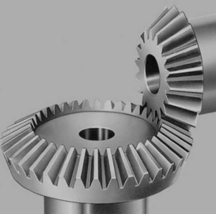
2.1 Introduction to Straight Bevel Gears
Straight bevel gears have a simple tooth profile compared to other bevel gears, making them easier to design, manufacture, and install. They are widely used due to their lower production costs.
2.2 Formation Principle and Tooth Surface Equation of Straight Bevel Gears
The tooth surface of a straight bevel gear is formed by the envelope of a series of generating lines on a conical surface. The involute tooth profile is commonly used due to its advantages such as smooth meshing, good load-carrying capacity, and easy manufacturing.
Equation of Involute on Conical Surface:
r=rb+uθ(u=radial parameter,θ=angular parameter)
Where rb is the base radius of the involute, and u and θ are parameters that determine the position on the involute.
2.3 Parametric Design of Straight Bevel Gears
Parametric design allows for the generation of different gear models by varying specific parameters. Using parametric design software such as SolidWorks, the three-dimensional model of a straight bevel gear can be created by driving dimensions with equations. By changing the characteristic parameters, the required three-dimensional model of the straight bevel gear can be generated, providing versatility.
3. Gear Hobbing Process for Straight Bevel Gears and Structural Design of Conical Hob
3.1 Traditional Machining Methods for Straight Bevel Gears
Traditional machining methods for straight bevel gears include planing, milling, and broaching, which have limitations in terms of efficiency and accuracy.
3.2 Meshing and Transmission Principle of Straight Bevel Gears
The meshing and transmission principle of straight bevel gears involves the contact and relative motion between the teeth of two gears with conical tooth surfaces.
3.3 Gear Hobbing Process for Straight Bevel Gears
Based on the meshing and transmission principle of straight bevel gears and the generative machining principle, a gear hobbing process for straight bevel gears is proposed. This method involves the use of a conical hob to continuously generate the tooth profile of the straight bevel gear.
3.4 Structural Design of Conical Hob
The structural design of the conical hob requires consideration of factors such as material, tooth profile, and geometric dimensions. Finite element analysis (FEA) is used to analyze the static and modal characteristics of the conical hob, ensuring its structural integrity and performance during the hobbing process.
Table 3: Key Parameters for Conical Hob Design
| Parameter | Description |
|---|---|
| Material | Tool steel (e.g., HSS, carbide) |
| Tooth Profile | Involute tooth profile |
| Helix Angle | Determines the direction of cutting |
| Flute Spacing | Affects chip removal and tool strength |
3.5 Static and Modal Analysis of Conical Hob
Static analysis is conducted to determine the stress distribution and deformation of the conical hob under different loading conditions. Modal analysis is used to identify the natural frequencies and mode shapes of the conical hob, avoiding resonance during the hobbing process.
3.6 Dynamic Contact Analysis between Conical Hob and Straight Bevel Gear
Finite element models of the conical hob and straight bevel gear are constructed, and constraints and boundary conditions are applied. Dynamic contact analysis is performed to investigate the contact stress distribution and variation trends during the meshing process.
4. NC Machining Simulation of Straight Bevel Gears Based on VERICUT
4.1 Introduction to VERICUT
VERICUT is a powerful software tool employed for NC (Numerical Control) machining simulation and verification. This software facilitates the simulation of the entire machining process, offering a pre-emptive check for potential issues such as collisions and tool interference. By utilizing VERICUT, manufacturers can detect and rectify these problems before actual machining commences, thereby enhancing production efficiency and reducing costs associated with machining errors.
4.2 Construction of Machining Simulation Model
The construction of the machining simulation model in VERICUT is a crucial step in the simulation process. Based on the meticulously designed conical hob structure and the straight bevel gear hobbing process, the NC machining G-code is generated to guide the simulation.
4.2.1 Establishment of Axis Motion for Hobbing Process
To simulate the hobbing process accurately, it is essential to establish the motion relationships among the various axes involved. This includes defining the movement of the workpiece, the conical hob, and the machine tool axes. By accurately modeling these axis motions, VERICUT can simulate the hobbing process in a virtual environment, providing a realistic preview of the actual machining operation.
4.2.2 Creation of Tool Model
The creation of the conical hob model is a vital component of the simulation setup. In VERICUT, the three-dimensional model of the conical hob, designed based on the gear tool design principles and the hobbing process requirements, is imported. This model ensures that the simulation accurately reflects the physical characteristics of the actual tool used in the hobbing process.
4.2.3 NC Machining G-code Generation
The NC machining G-code is the set of instructions that governs the movement of the machine tool during the hobbing process. Based on the designed conical hob structure and the straight bevel gear hobbing principles, the G-code is generated. This code includes instructions for axis movements, tool engagement, and feed rates, among others. The G-code is then loaded into VERICUT to drive the simulation of the hobbing process.
By integrating these elements, a comprehensive NC machining simulation model for straight bevel gears based on VERICUT is established. This model allows for the detailed analysis and verification of the hobbing process, ensuring that potential issues are detected and addressed before actual production commences. The simulation results provide valuable insights into the feasibility and effectiveness of the proposed straight bevel gear hobbing method.