
Gear system dynamics is a discipline to study the dynamic behavior of gear system in the process of transmitting motion and power. It takes the whole gear system as the research object, and can comprehensively study the dynamic performance of gear system. Therefore, this chapter introduces the nonlinear gear dynamic model with six degrees of freedom which is established by using the lumped parameter method, and introduces the gear system dynamic model, the calculation method of gear meshing stiffness and the gear sliding friction model.
For the involute spur gear face contact degree greater than 1 and less than 2, it is necessary to consider the meshing of two pairs of gears in a complete gear meshing cycle. The gear meshing process is shown in the figure
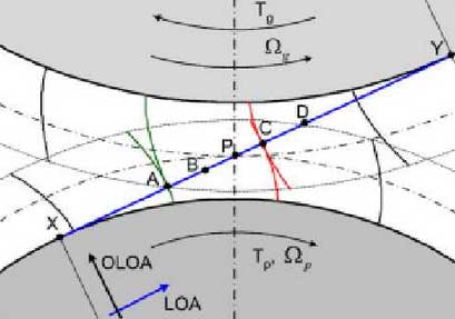
The driving gear rotates clockwise around the central axis of the driving gear under the action of torque TP, and the driven gear rotates anticlockwise around the central axis of the driven gear under the action of load TG. On the theoretical meshing line XY (along the direction of oloa), points x and y are the tangent points of the gear meshing line and the base circle of the driving and driven gears respectively, and the line ad is the actual track of the meshing point of the gear tooth profile, which is called the actual meshing line.
At the beginning of the gear meshing cycle (i.e. t = 0), gear pair I is engaged at point a, and gear pair II is engaged from the highest point C of single tooth meshing (gear pair I is defined as the pair of teeth engaging along the meshing line AC, and gear pair II is defined as the pair meshing along the meshing line CD). With the rotation of the gear, when the tooth pair I is engaged to the lowest point B of single tooth meshing (i.e., t = TB) )The tooth pair II reaches the meshing point D and is out of engagement. Next, the gear enters the single tooth meshing area, and only the gear pair I is engaged. The process goes from meshing point B to meshing point C. When the gear teeth pair I mesh through the node P (i.e. t = TP), the relative sliding speed of the driving gear will be reversed, which will lead to the reverse sliding friction force on the tooth surface. This will provide a pulse friction excitation for the gear dynamic system. Finally, the tooth pair I passes through the highest point C of single tooth engagement (i.e. t = TC), and a gear meshing cycle ends, and a new pair of teeth begins to mesh at point a.