
Abstract
Hypoid gears are widely utilized in aircraft, ships, machine tools, and heavy industries due to their high coincidence degree, strength, reliability, wear resistance, and transmission efficiency. This thesis focuses on the milling method of hypoid gears, aiming to enhance the understanding and application of this complex gear type. Through in-depth research, this study proposes an effective milling method and verifies its feasibility through theoretical derivation, simulation, and experimental validation.
1. Introduction
1.1 Background and Significance of the Research
The hypoid gear, characterized by its unique tooth surface geometry and high transmission efficiency, plays a crucial role in various mechanical systems. The traditional cutting methods for hypoid gears, however, often involve complex machinery and costly tools. Therefore, there is a need to explore more efficient and cost-effective milling methods.
The significance of this research lies in developing a new milling method for hypoid gears that simplifies the machine tool movements and reduces the complexity of the cutting tools. This, in turn, can lead to improved production efficiency and cost savings in the manufacturing of hypoid gears.
1.2 Research Status at Home and Abroad
Research on hypoid gear cutting methods has been ongoing for decades. E. Wildhaber, in his articles published in the American Machinist, provided a comprehensive description of the geometry and kinematics of hypoid gears. Litvin and Gutman further studied the methods of forming hypoid gears, proposing the “forming method” and “spiral forming method.” They established mathematical models and utilized face milling and tooth contact analysis (TCA) for tooth surface contact analysis and local synthesis.
In China, research on hypoid gears started relatively late due to the late development of the machinery industry. However, significant progress has been made in recent years. Scholars have conducted in-depth research on Gleason gear cutting technology and TCA, laying a solid foundation for subsequent research on hypoid gears.
1.3 Main Research Content
This thesis focuses on the milling method of hypoid gears, including the derivation of gear cutting equations, processing simulation, and experimental validation. The specific research contents are as follows:
- Elucidate the basic principle of the generating-line cutting method for involute gears and demonstrate its feasibility for hypoid gear cutting. Derive the cutting equations for both the large and small gears of the hypoid gear pair.
- Conduct curve fitting on the cutting area on the corresponding gear base plane to facilitate the cutting process. Derive the gear cutting motion equations and write the NC program. Establish a VERICUT machine model based on the existing CNC spiral bevel gear milling machine, and perform simulation processing to verify the feasibility of the generating-line cutting method.
- Design the tooth blanks for both the large and small gears of the hypoid gear pair, purchase the raw materials, and precision-machine them into the required shapes.
2. Principle of Hypoid Gear Transmission
The detailed explanation of the transmission principle of hypoid gears, including the definition, characteristics, and advantages of hypoid gears. It also introduces the basic concepts and terminology related to hypoid gear cutting, such as base cone, base plane, and tooth surface generation.
3. Milling Method of Hypoid Gears
3.1 Basic Principle of Generating-Line Cutting Method
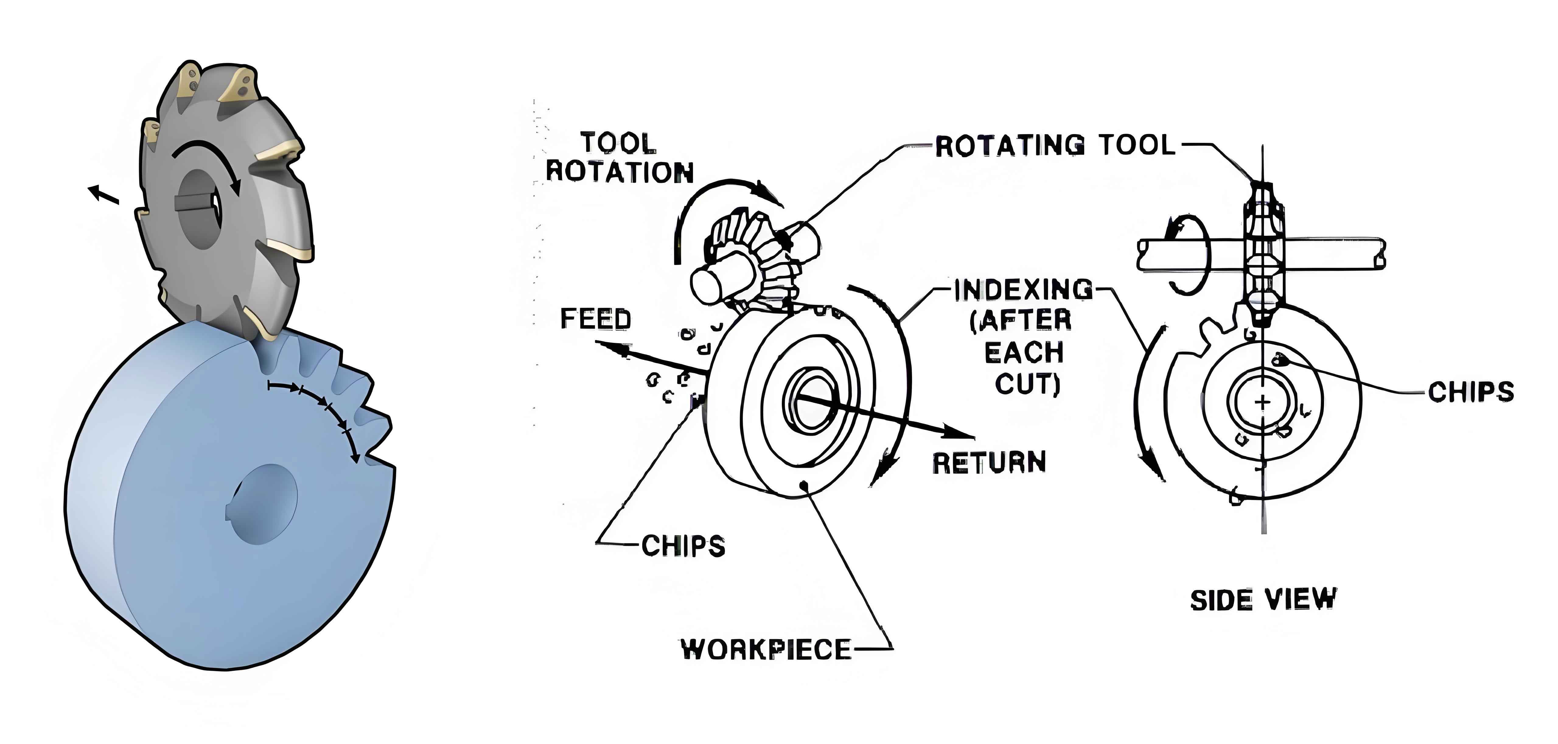
The generating-line cutting method for hypoid gears involves using a tooth surface contact line to configure the cutting tool and providing the cutting machine tool movement conditions according to the movement during the formation of the meshing surface. This method simplifies the required machine tool movements and cutting tools, making it more efficient and cost-effective.
3.2 Derivation of Cutting Equations
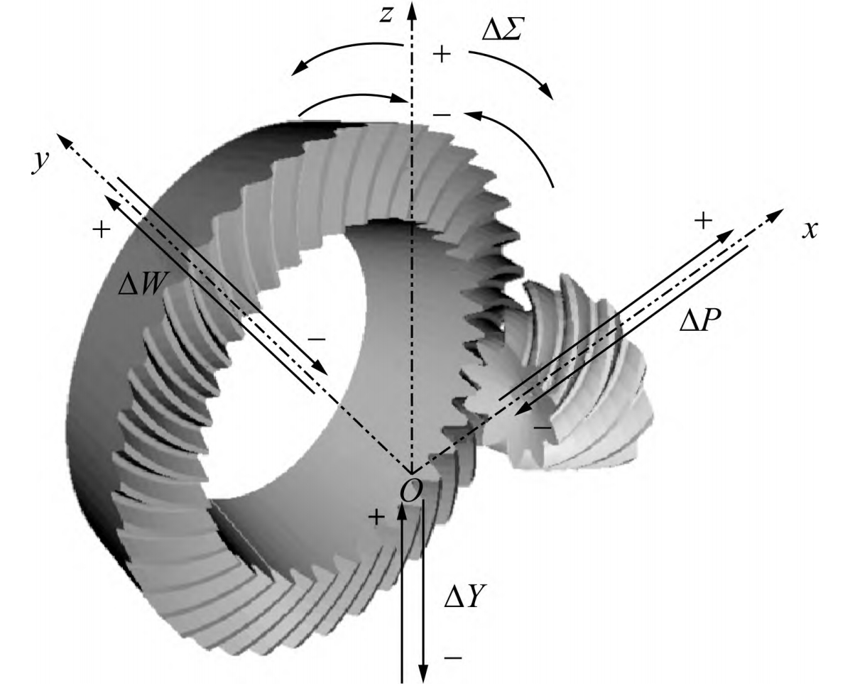
The derivation of cutting equations for hypoid gears involves several complex steps, including determining the initial position of the tooth blank in the coordinate system, finding the relationship between the longitudinal coordinate of the end or starting point of the generating line along the tooth root and the direction angle of the tooth blank, and solving for the cutting-out position in the processing coordinate system.
Table 1: Summary of Cutting Equation Derivation Steps
| Step | Description |
|---|---|
| 1 | Determine the initial position of the tooth blank in the coordinate system |
| 2 | Find the relationship between the longitudinal coordinate of the generating line and the direction angle of the tooth blank |
| 3 | Solve for the cutting-out position in the processing coordinate system |
| 4 | Derive the cutting motion equations for both the large and small gears |
3.3 Curve Fitting on Cutting Area
To facilitate the cutting process, curve fitting is performed on the cutting area on the corresponding gear base plane. This allows for a smoother and more accurate cutting path, reducing the complexity of the cutting process.
4. Simulation of Hypoid Gear Cutting
4.1 Simulation Using CATIA
CATIA software is used for automatic programming in the simulation process. The tooth blank is first drawn in the CATIA sketch with a certain length and a base circle radius of 220mm. The boundary lines required for cutting the large gear tooth blank are then drawn on this cylinder. The cutting tool is selected based on actual conditions, and the cutting starting and ending points are set. Finally, the simulation processing of the large gear tooth blank is performed in CATIA, and the NC code program is automatically generated.
4.2 Verification of Cutting Feasibility
The generated NC code program is then imported into the CNC machine tool for actual cutting of the nylon tooth blank of the large gear. The simulation results are compared with the actual cutting results to verify the feasibility of the generating-line cutting method.
5. Experimental Validation
5.1 Preparation of Experimental Equipment and Materials
The experimental equipment includes a CNC spiral bevel gear milling machine, a VERICUT simulation software, and various measuring instruments. The materials used include nylon rods for tooth blanks and cutting tools.
Table 2: List of Experimental Equipment and Materials
| Equipment/Material | Description |
|---|---|
| CNC spiral bevel gear milling machine | Used for actual cutting of hypoid gears |
| VERICUT simulation software | Used for simulation processing and verification of cutting feasibility |
| Measuring instruments | Used for measuring the accuracy of the cut gear teeth |
| Nylon rods | Used as tooth blanks for cutting experiments |
| Cutting tools | Used for cutting the tooth blanks into the required shapes |
5.2 Cutting Experiments
The cutting experiments involve several steps, including tool selection, setting up the machine, adjusting the coordinates, and performing the actual cutting. The cutting process is monitored closely to ensure that it proceeds smoothly and accurately.
5.3 Measurement and Analysis of Experimental Results
After the cutting experiments, the accuracy of the cut gear teeth is measured using various measuring instruments. The measurement results are analyzed to assess the feasibility and accuracy of the generating-line cutting method.
6. Conclusion and Future Work
6.1 Conclusion
This thesis proposes a new milling method for hypoid gears based on the generating-line cutting method. Through theoretical derivation, simulation, and experimental validation, it is demonstrated that this method is feasible and can effectively reduce the complexity of the cutting process and improve production efficiency.
6.2 Future Work
Future research can focus on optimizing the cutting parameters and improving the accuracy of the cut gear teeth. Additionally, the application of advanced manufacturing technologies, such as additive manufacturing and precision machining, can be explored to further enhance the production efficiency and quality of hypoid gears.