
Throughout my career in mechanical engineering, I have devoted considerable effort to the plotting and calculation of gears, particularly the involute cylindrical straight spur gear. This type of gear is fundamental to countless mechanical systems, from mining machinery to precision instruments. The process of reverse-engineering a gear from a physical sample — determining its module, pressure angle, addendum modification coefficient, and other parameters — is both an art and a science. In this article, I share my systematic approach, supported by real-world examples and extended applications, to demonstrate how gear plotting can be performed accurately and reliably, even under challenging conditions.
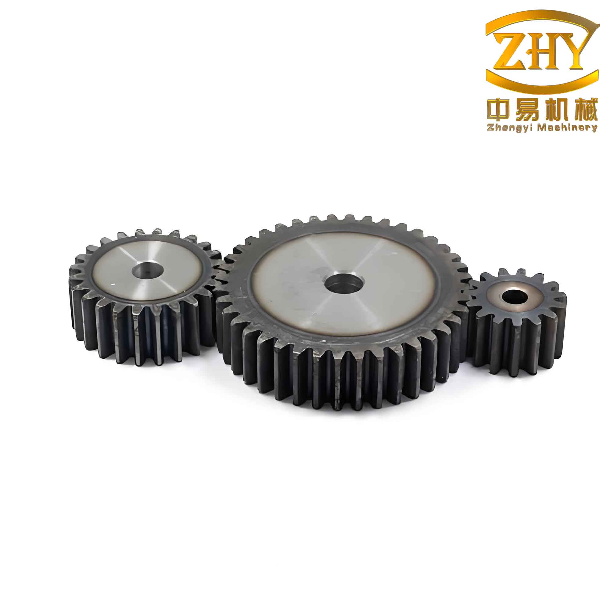
The straight spur gear, with its teeth parallel to the axis, is the simplest and most widely used type of gear. Its analysis requires knowledge of five essential parameters: number of teeth $z$, module $m$ (or diametral pitch $DP$), pressure angle $\alpha$, center distance $a$, and addendum modification coefficient $x$. The number of teeth can be counted directly. The remaining parameters must be derived through careful measurement and calculation.
Key Steps in Straight Spur Gear Plotting
I begin by measuring the base pitch $P_b$ using the common normal (base tangent) length method. This is the most accurate way to determine the pressure angle and module. The procedure is as follows:
- Estimate the number of teeth to span, $k$, using the formula for a straight spur gear:
$$
k = \frac{z}{9} + 0.5 \quad \text{(round to nearest integer)}
$$
Measure the common normal lengths $W_{k-1}$, $W_k$, and $W_{k+1}$ using a micrometer or caliper. At least two consecutive measurements are needed to compute the base pitch:
$$
P_b = W_k – W_{k-1}
$$
Repeat for the mating gear if available. The base pitch must be identical for both gears of a pair. By comparing the measured $P_b$ with standard values (see Table 1), I can identify the module (metric) or diametral pitch (inch) and the pressure angle.
| Module $m$ (mm) | Diametral Pitch $DP$ (in⁻¹) | Pressure Angle $\alpha$ (°) | Base Pitch $P_b$ (mm) |
|---|---|---|---|
| 2 | — | 20 | 5.904 |
| 3 | — | 20 | 8.856 |
| 4 | — | 20 | 11.808 |
| — | 3 | 20 | 9.929 |
| — | 3 | 25 | 9.455 |
| — | 4 | 20 | 7.447 |
Once the module/pitch and pressure angle are known, the addendum modification coefficient $x$ can be derived from the measured common normal length using:
$$
x = \frac{W’ – W^*}{2m\sin\alpha}
$$
where $W’$ is the measured common normal length and $W^*$ is the theoretical length for a zero-shift gear of the same number of teeth. Since $W^*$ depends on $z$, $m$, and $\alpha$, I compute it from standard formulas.
Finally, I validate the entire set of parameters by recalculating the tip diameter $d_a$, root diameter $d_f$, and center distance $a$, and comparing them with the measured values. This iterative check ensures consistency.
Example 1: American Inch-System Straight Spur Gear (Diametral Pitch)
I was once tasked with plotting a pair of straight spur gears from an American-made gearbox used in mining equipment. The measured data were:
| Gear | $z$ | $W_{k}$ (mm) | $W_{k+1}$ (mm) | $d_a$ (mm) | $d_f$ (mm) |
|---|---|---|---|---|---|
| Pinion | 26 | $W_4 = 90.76$ | $W_5 = 114.86$ | 238.4 | 197.0 |
| Gear | 37 | $W_5 = 116.41$ | $W_6 = 140.52$ | 329.8 | 288.5 |
Center distance $a’ = 267.0$ mm. First, I computed base pitches:
$$
P_{b1} = 114.86 – 90.76 = 24.10 \text{ mm}
$$
$$
P_{b2} = 140.52 – 116.41 = 24.11 \text{ mm}
$$
These values match the standard base pitch for diametral pitch $DP = 3$ and pressure angle $\alpha = 25^\circ$ (see Table 1). The American system often uses $25^\circ$ pressure angle for heavy-duty straight spur gears. With $m = 25.4 / DP = 8.4667$ mm equivalent module.
I then computed the addendum modification coefficients. For the pinion using $W_4$ and $W_5$:
$$
x_1 = \frac{90.76 – W_4^*}{2 \times 8.4667 \times \sin 25^\circ}
$$
Carrying out the calculations gave $x_1 \approx 0.058$ from both measurements (average 0.0583). For the gear, $x_2 \approx -0.0780$. However, these raw values did not account for backlash. Using the measured center distance $a’$, I determined the total modification sum:
$$
\sum x = \frac{a’ – \frac{m(z_1+z_2)}{2}}{m} = \frac{267 – \frac{8.4667(26+37)}{2}}{8.4667} \approx 0.0355
$$
The raw sum was $0.0583 – 0.0780 = -0.0197$, a difference of $0.0552$. I distributed this equally, obtaining refined $x_1 = 0.0859$ and $x_2 = -0.0505$.
Validation using the American standard ($h_a^* = 1$, $c^* = 0.4$) yielded:
$$
d_{a1} = m(z_1 + 2h_a^* + 2x_1) = 8.4667(26 + 2 + 0.1718) = 238.5 \text{ mm (measured 238.4)}
$$
$$
d_{f1} = m(z_1 – 2h_a^* – 2c^* + 2x_1) = 8.4667(26 – 2 – 0.8 + 0.1718) = 197.8 \text{ mm (measured 197.0)}
$$
The close agreement confirmed the correctness of the straight spur gear parameters.
Example 2: German Metric Straight Spur Gear
Another project involved a single German-made straight spur gear with $z=21$. Measured data:
| Parameter | Value (mm) |
|---|---|
| $W_3$ | 160.6 |
| $W_4$ | 219.56 |
| $d_a$ | 481.5 |
| $d_f$ | 383.2 |
Base pitch: $P_b = 219.56 – 160.6 = 58.96$ mm. This corresponds exactly to module $m=20$ mm with $\alpha=20^\circ$ ($P_b = \pi m \cos\alpha = 59.04$ mm, very close). Thus the gear is a metric straight spur gear.
Computing the addendum modification coefficient from $W_3$ and $W_4$ gave $x \approx 0.5168$ (average). I adjusted slightly by $+0.01$ to account for typical wear, leading to $x = 0.5268$.
Initially, using German standard $h_a^*=1$, $c^*=0.167$ gave tip diameter $d_a = 20(21 + 2\times1 + 2\times0.5268) = 473.86$ mm, far below the measured 481.5 mm. Root diameter $d_f = 20(21 – 2\times1 – 2\times0.167 + 2\times0.5268) = 394.79$ mm, also higher than measured 383.2 mm. This large discrepancy suggested the gear used a different tooth profile.
After consulting the machine’s technical documentation, I learned the mating gear had $z=13$ and the center distance was 359.6 mm. The computed contact ratio was only 1.15, which is marginal. To improve smoothness, the designer likely adopted a larger addendum coefficient. I tried $h_a^* = 1.2$ and $c^* = 0.267$ (allowing for a grinding allowance). Recalculating:
$$
d_a = 20(21 + 2\times1.2 + 2\times0.5268) = 481.86 \text{ mm (measured 481.5)}
$$
$$
d_f = 20(21 – 2\times1.2 – 2\times0.267 + 2\times0.5268) = 382.39 \text{ mm (measured 383.2)}
$$
The errors are less than 0.5 mm, well within acceptable tolerances. This example emphasizes that for a straight spur gear, one must be prepared to adjust standard tooth proportions based on observed dimensions and application requirements.
Integrating Wireless Wear Monitoring and Abrasive Waterjet Cutting
Beyond the classic gear plotting described above, modern engineering often demands real-time condition monitoring and efficient material processing. I have also been involved in projects that combine these technologies with straight spur gear applications. For instance, in shield tunneling machines, the cutterhead wear is critical. A system based on the MSP430 microcontroller and CC1101 radio-frequency module was developed to monitor the wear of disc cutters wirelessly. The system uses eddy-current sensors to detect the displacement of a metal block attached to the cutter, which indirectly reflects the wear state of the cutter. This non-contact measurement method provides high accuracy (error less than 0.16 mm) and reliability in harsh underground environments. The principles of data acquisition, power management (timed wake-up and interrupt-based sleep), and wireless transmission are analogous to the measurement techniques used in gear inspection, where precise dimensional data must be captured and communicated.
Another application is the recovery of deformed I-section steel beams used in underground mine roadway supports. Traditional manual cutting is inefficient and dangerous. I have explored the use of pre-mixed abrasive waterjet (AWJ) technology to cut bent I-beams quickly and safely. The test results showed that AWJ cutting can adapt to complex underground conditions, meeting safety standards while significantly improving recovery rates. Although this example does not directly involve straight spur gears, the same engineering mindset — systematic measurement, parameter determination, and validation — applies. In gear plotting, we determine module, pressure angle, and modification coefficients. In AWJ cutting, we determine pressure, abrasive flow rate, and traverse speed. Both rely on empirical formulas and iterative checking.
Conclusion
From my extensive hands-on experience, the plotting and calculation of straight spur gears is a methodical process that requires careful measurement of common normal lengths, base pitch identification, addendum modification coefficient derivation, and geometric verification. The two examples — an American DP3/25° gear pair and a German m20/20° single gear — illustrate the common pitfalls and how to resolve them using validation with tip/root diameters and center distance. The addition of modern monitoring and processing technologies, such as wireless wear sensors and abrasive waterjet cutting, demonstrates that the fundamental skills of parameter determination remain vital across many mechanical engineering domains. By mastering these techniques, we can reliably reverse-engineer and reproduce straight spur gears for maintenance, repair, and manufacturing, ensuring the longevity and performance of critical machinery.