
In my extensive experience within precision gear manufacturing, gear shaving stands out as a critical finishing operation performed prior to final heat treatment. Its widespread adoption in processes like hobbing followed by gear shaving is attributed to high accuracy, excellent productivity, and relatively straightforward machine setup. However, the gear shaving process is a complex interplay of multiple factors. The final quality of the gear shaved component can be compromised by issues related to workpiece blank accuracy, machine and fixture precision, tool design, cutter modification, and cutting parameters. This article, drawn from my first-hand observations and technical practice, delves into the common problems encountered during gear shaving, analyzes their root causes, and provides systematic solutions. I will emphasize the term “gear shaving” throughout to reinforce the process’s central role.
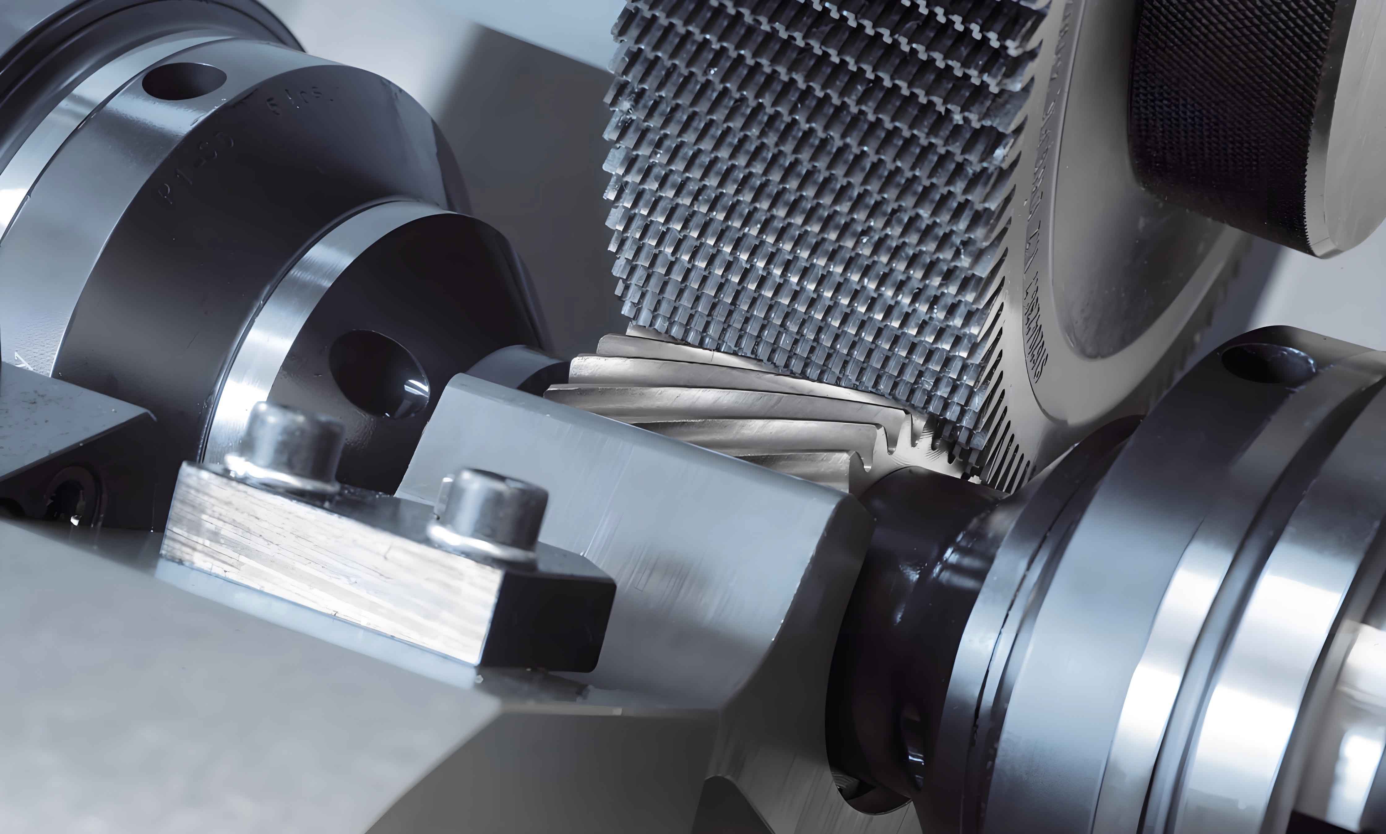
The fundamental principle of gear shaving involves a crossed-axes meshing between the shaving cutter and the workpiece gear. This generates a sliding motion along the tooth flanks, which is the primary cutting action. The quality of this interaction determines the final gear geometry and surface finish. Let’s explore the typical defects.
1. S-Shaped Tooth Profile (Profile Concavity)
One of the most prevalent and tricky issues in gear shaving is the development of an S-shaped or concave tooth profile. This irregular form directly impacts gear meshing noise and load distribution.
Cause Analysis: During the gear shaving process, the contact points between the shaving cutter and the workpiece gear change continuously. As illustrated in the conceptual diagram, the gear teeth experience varying force magnitudes at different contact zones—typically categorized as even-numbered and odd-numbered contact points. This leads to non-uniform material removal. Generally, profile error is minimal at even-numbered contact zones but increases at odd-numbered zones, resulting in the characteristic mid-profile concavity. The primary contributors are suboptimal shaving cutter design and modification that lead to poor meshing conditions. The axis crossing angle is a key parameter here. The radial velocity component, which influences cutting, is zero at the base circle and maximum at the tooth tip. An improper axis angle can exacerbate the uneven force distribution. The force dynamics can be simplified for analysis. The resultant cutting force at a tooth flank has tangential and radial components. An imbalance, often related to the number of simultaneous contact points, causes differential material removal. The condition for optimal contact can be related to the number of contact points $N_c$:
$$ N_c = \frac{Z_g + Z_s}{2} $$
where $Z_g$ is the number of workpiece gear teeth and $Z_s$ is the number of shaving cutter teeth. An even $N_c$ is often desirable. The pressure distribution $P(x)$ along the profile height $x$ is non-uniform, leading to a material removal rate $MRR(x)$ proportional to it and the sliding velocity $V_s(x)$:
$$ MRR(x) \propto P(x) \cdot V_s(x) \cdot \mu $$
where $\mu$ is a coefficient of friction. Concavity occurs when $MRR(x)$ is higher in the mid-region than at the tip and root.
Solutions and Preventive Measures:
| Solution Area | Specific Action | Technical Rationale |
|---|---|---|
| Cutter Design | Adhere to design rules optimizing meshing state. Aim for longer even-contact zones and shorter odd-contact zones. Avoid mismatches between cutter tip diameter and workpiece root, excessive cutter addendum, and unsuitable modification curves. | Ensures uniform load distribution and minimizes force variations during the gear shaving cycle. |
| Cutter Modification | Apply reverse modification to the shaving cutter profile based on the measured error on the gear shaved workpiece. Modification points should correspond to the profile variation areas. The modification amount $\Delta_m$ is typically: $$ \Delta_m = k \cdot \Delta_d $$ where $\Delta_d$ is the deformation error on the gear (0.67 ≤ k ≤ 1). For severe cases, use multi-segment modification. | Actively compensates for the inherent process deflection and elastic recovery of the workpiece material during gear shaving. |
| Process Parameters | Select an appropriate axis crossing angle $\Sigma$. For medium-module gears, an angle of 12° often yields the best results for gear shaving quality. | Optimizes the sliding velocity components for effective cutting across the entire profile. |
2. Rough or Scratched Tooth Surface (Surface Tearing)
Achieving a fine surface finish is a primary goal of gear shaving. Surface defects like radial scratches, longitudinal grooves, and general roughness are common failures.
Cause Analysis and Manifestations:
- Radial Scratches at Tooth Tip: Caused by an excessively small axis crossing angle $\Sigma$ during gear shaving. This leads to a large radial velocity component $V_r$ and a small axial (lengthwise) velocity component $V_a$ at the tip, resulting in poor cutting action and ploughing. Excessively high cutter speed can have a similar effect. The radial velocity is given by: $$ V_r = V \cdot \sin(\Sigma) \cdot \sin(\beta) $$ where $V$ is the cutting speed and $\beta$ is the helix angle.
- Longitudinal Grooves (Cutter Lead Marks): Occur when the workpiece axial feed per revolution $f_a$ coincides with the shaving cutter’s groove pitch $p_g$. This resonant condition causes the cutter grooves to repeatedly track the same path on the gear flank.
- General Surface Roughness and Scratches: Attributed to irrational chip flute arrangement on the cutter, a dull cutter edge, improper axis angle, large radial runout during cutter grinding, magnetic chips adhering to the cutter, or chips clogging the flutes. High cutter rotational speed can also be detrimental. Furthermore, soft workpiece material, large module/helix angle, poor cutting fluid, and cutter edge defects exacerbate all these issues.
Solutions and Preventive Measures:
| Parameter Category | Recommended Setting/Range | Impact on Gear Shaving |
|---|---|---|
| Axis Crossing Angle ($\Sigma$) | 10° to 15° (12° ideal for medium module) | Balances radial and axial sliding for effective cutting and minimizes tip scratching. |
| Cutting Speed ($v_c$) | ~110 m/min. Control via cutter spindle speed $n$: $$ n = \frac{1000 \cdot v_c}{\pi \cdot d_s} $$ where $d_s$ is cutter diameter. For medium modules, $n$ ≈ 145-175 rpm. | Ensures efficient chip formation without excessive heat or built-up edge during gear shaving. |
| Worktable Feed Rate ($v_f$) | 100 – 150 mm/min (longitudinal). Avoid $f_a = p_g$. | Prevents lead mark patterns and ensures uniform material removal across the face width in the gear shaving pass. |
| Radial Infeed per Stroke ($f_r$) | 0.02 – 0.04 mm/stroke | Controls load on cutter teeth, balancing surface quality and tool life in the gear shaving operation. |
| Workpiece Material | Ensure proper pre-hardness via quenching and tempering or normalizing. | Improves machinability, reduces material adhesion to the gear shaving cutter edge. |
| Cutter Maintenance | Regrind promptly when dull. Discard if flute depth < 0.40 mm. Ensure edges are sharp, free of burns, cracks, and chips. | Maintains the sharp cutting action essential for effective gear shaving. |
| Cutting Fluid | Use high-lubricity fluids (e.g., mineral oil with EP additives, extreme pressure emulsion). Avoid water-based fluids. Keep clean. | Reduces friction, cools the cutting zone, and flushes chips away in the gear shaving process. |
3. Heel Buildup (Root Step)
This defect appears as a ridge or step along the face width at the transition between the active tooth flank and the root fillet. It is highly detrimental, causing noise, vibration, and even assembly or tooth breakage issues.
Cause Analysis: The root cause is interference between the tip of the gear shaving cutter and the root of the workpiece gear during the meshing cycle. This can be due to: 1) Poor shaving cutter design, such as using excessive negative profile shift. 2) Incorrect cutter regrinding, where the cutter’s tip diameter $d_{as}$ and tooth thickness no longer match the intended geometry, causing the tip to rub or dig into the gear root. 3) Issues with the pre-shaving (e.g., hobbing) process: improper pre-shave hob geometry, worn hob protuberance, excessive shaving stock, or a “step” left in the root from unilateral hob setting.
Solutions and Preventive Measures: The solution focuses on ensuring the gear shaving cutter tip moves freely within the gear’s root undercut area. The condition to avoid interference can be checked using the geometry of engagement. The limiting diameter of the shaving cutter tip $d_{a,s}^{max}$ should satisfy:
$$ d_{a,s}^{max} \leq d_{f,g} + 2 \cdot ( \rho_{f,g} + \delta ) $$
where $d_{f,g}$ is the gear root diameter, $\rho_{f,g}$ is the root fillet radius, and $\delta$ is a safety clearance. Key actions include:
- Cutter Design: Prefer a positive or neutral profile shift for the gear shaving cutter to create a “fatter” root and sharper tip, increasing the working pressure angle and avoiding interference.
- Cutter Regrinding: Strictly follow the re-grinding parameter curve to maintain the correct relationship between tip diameter and tooth thickness.
- Pre-Shave Process Control: Strictly control shaving stock allowance. Maintain the pre-shave hob’s protuberance and regrind it timely. Ensure the hob setting avoids leaving a one-sided root step.
4. Shaving Cutter Tooth Chipping or Breakage
Sudden failure of cutter teeth disrupts production and can damage the workpiece.
Cause Analysis: This is typically a result of overloading during gear shaving. Common causes include: burrs on the pre-shave gear teeth acting as impact points, excessive shaving stock allowance, overly aggressive cutting parameters (high cutting speed $v_c$ or feed rate $v_f$), or a lack of cutting fluid.
Solutions and Preventive Measures:
| Control Point | Action |
|---|---|
| Pre-Shave Deburring | Thoroughly remove all burrs from hobbed or shaped gears before gear shaving. |
| Stock Allowance | Minimize the total stock for gear shaving. Typical values are often in the range of 0.05-0.15 mm on the tooth thickness, depending on module and size. |
| Cutting Parameters | Use moderate, proven parameters for speed and feed as outlined in the surface quality section. The radial force $F_r$ during gear shaving should be monitored: $$ F_r \propto f_r^{a} \cdot v_c^{b} $$ where exponents $a$ and $b$ are material-dependent. Keeping $f_r$ and $v_c$ within recommended ranges controls $F_r$. |
5. Excessive Pitch Error
The gear shaving process has a limited ability to correct pitch-related errors like pitch deviation $f_{pt}$, single pitch error $f_p$, and pitch cumulative error $F_p$. It can even transform radial runout $F_r$ into span error.
Cause Analysis: The inherent kinematics of gear shaving, which is a free-meshing process without a rigid mechanical link like in hobbing, means it cannot generate a new index. It primarily improves profile and lead. Therefore, if the pre-shave gear has significant pitch errors or radial runout, gear shaving will not eliminate them. Additionally, errors in the shaving machine’s indexing system, fixture accuracy (e.g., centering), and tailstock alignment contribute directly to final pitch errors.
Solutions and Preventive Measures: The strategy is to control errors at the source and ensure machine stability.
- Pre-Shave Gear Quality: Stringently control the pitch accuracy and radial runout of the gear before it enters the gear shaving operation. The capability of the gear shaving process to improve pitch is minimal, so the incoming quality must be high.
- Machine and Fixture Maintenance: Ensure the shaving machine’s indexing mechanism, drive train, and spindle bearings are in good condition. Maintain high accuracy for the workpiece arbor, centers, and clamping devices. The concentricity error $\Delta C$ between centers should be minimized: $$ \Delta C < 0.005 \cdot m_n $$ where $m_n$ is the normal module, as a rule of thumb.
- Process Planning: Understand that gear shaving is for finishing, not correcting gross geometry errors. The process sequence (e.g., hobbing -> heat treat -> hard finishing) must be chosen appropriately based on final requirements.
Fundamental Metal Cutting Principles Relevant to Gear Shaving
To fully master and troubleshoot the gear shaving process, a solid grounding in metal cutting theory is indispensable. Gear shaving is, at its core, a sophisticated cutting operation. Key principles include:
Workpiece Material Machinability: The ease of cutting, or machinability, directly influences gear shaving results. Materials are often ranked on a 12-grade scale from easy to difficult to machine. Machinability affects the choice of all cutting conditions. For gear shaving common materials like case-hardening steels, the machinability index $K_v$ can guide parameter selection: $$ v_{c,mat} = K_v \cdot v_{c,ref} $$ where $v_{c,ref}$ is the speed for a reference material.
Cutting Tool Materials: The selection of shaving cutter material is crucial. Modern gear shaving cutters are predominantly made from premium high-speed steels (HSS) or powdered metals. Their performance in terms of hot hardness, wear resistance, and toughness dictates their life and the surface quality they can produce in gear shaving. The Taylor tool life equation is a fundamental concept: $$ v_c \cdot T^n = C $$ where $T$ is tool life, $n$ is the Taylor exponent (material-dependent), and $C$ is a constant. For gear shaving cutters, a high $n$ value indicates less sensitivity to speed changes.
Geometry of Cutting: The complex geometry of the gear shaving cutter tooth – its rake angles $\gamma$, relief angles $\alpha$, and the intricate form of the serrated edges – is designed to optimize the shearing and scraping action. The effective rake angle in the direction of cutting varies along the profile, influencing chip formation.
Chip Formation and Control: In gear shaving, chips are typically very fine and fragmented. Effective chip evacuation is vital to prevent scratching. The chip thickness $h$ in gear shaving is not constant and is related to the feed $f_r$ and the local curvature of the contacting surfaces.
By applying these universal metal cutting principles to the specific context of gear shaving, engineers and operators can make informed decisions that transcend simple trial-and-error, leading to more stable, efficient, and high-quality gear production. Every adjustment in the gear shaving process, from axis angle to feed rate, finds its theoretical justification in these fundamentals. Therefore, a deep and systematic understanding of both the unique mechanics of gear shaving and the broader theory of metal cutting is essential for anyone seeking to optimize this critical finishing process. The continuous pursuit of perfection in gear shaving rests on this dual foundation of practical experience and scientific principle.