1. Large tooth surface of spiral bevel gear Σ2 production and its equation
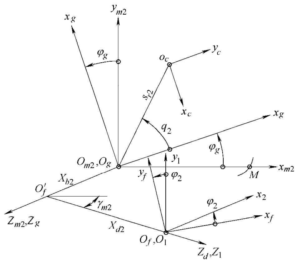
The double-sided hobbing method is generally used in the machining of large gear of spiral bevel gear, and the machining parameters generally have the same calculation method. Use the coordinate system shown in Figure 2 to describe the generation of gear tooth surface. The cutter head coordinate system SC (ocxcyczc) is located in the I quadrant of the shaking table coordinate system SG (ogxgygzg) and rotates 1.5 π around the Z axis. The initial position of SG coincides with the machine tool coordinate system SM2 (om2xm2ym2zm2), and its arbitrary instantaneous rotation angle relative to SM2 ϕ g. Then the corresponding generation angle of the large wheel is ϕ 2=m2g· ϕ g。 Other parameters γ M2 is the installation angle of wheel blank (equal to the cone angle of large wheel root), XB2 = | om2of ‘| is the bed, and xd2 = | of’ of | is the axial wheel position correction value. According to the meshing equation:
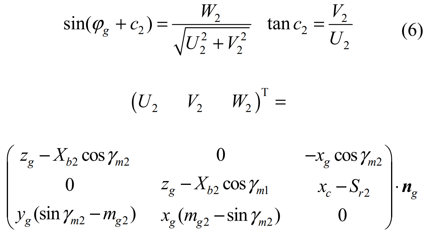
Shovel wheel equation:
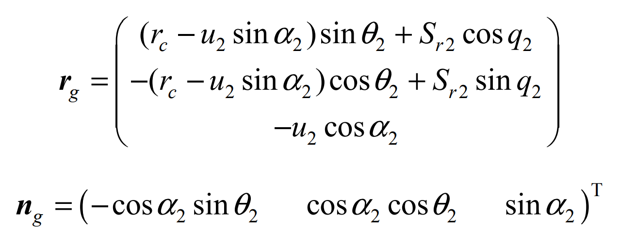
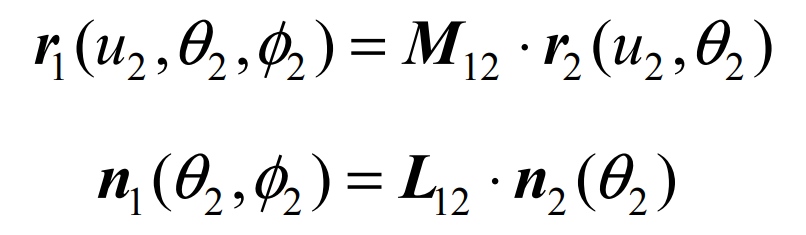
Where, α 2 is the tooth shape angle of the large wheel cutter head, the internal cutter is positive and the external cutter is negative. The tooth surface of the big wheel can be obtained by changing the coordinates Σ 2 equation.
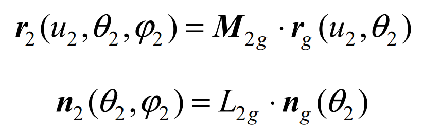
Where m2g and l2g respectively represent the homogeneous transformation and rotation transformation matrix of the coordinate system SG to S2 (in the case of homogeneous coordinate transformation, RG shall be taken as a four-dimensional vector).
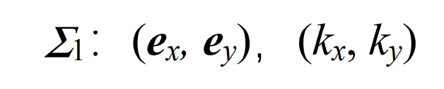
2. Tooth surface of conjugate pinion of spiral bevel gear Σ1
Based on the envelope principle that the tooth surface of the big gear is generated into the tooth surface of the small gear, it is assumed that the initial meshing angle of the large and small gears is φ 20、 φ 10, the relationship between the rotation angle of large and small wheels at any meshing position is:
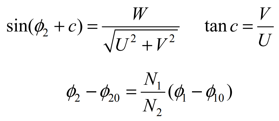
The form of each quantity is the same as that of the formula, which only needs to be replaced. Using the above relationship, the tooth surface of conjugate small wheel can be obtained Σ 1 equation:
3. Calculation of curvature parameters of conjugate pinion of spiral bevel gear by numerical differentiation
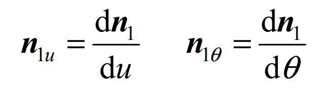
Given the large tooth surface of spiral bevel gear Σ 2 upper reference point m (U20, θ 20) Surface parameters of (after that, use U θ Replace) and give the differential Δ u、 Δθ Increment, calculate the numerical differentiation r1u, R1V and N1 by using the above formula θ、 n1 θ , Namely:
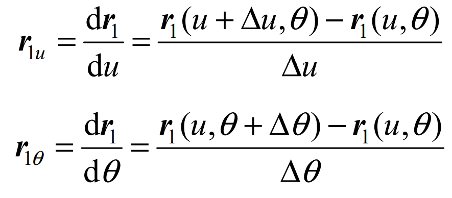
Similarly, we can find:
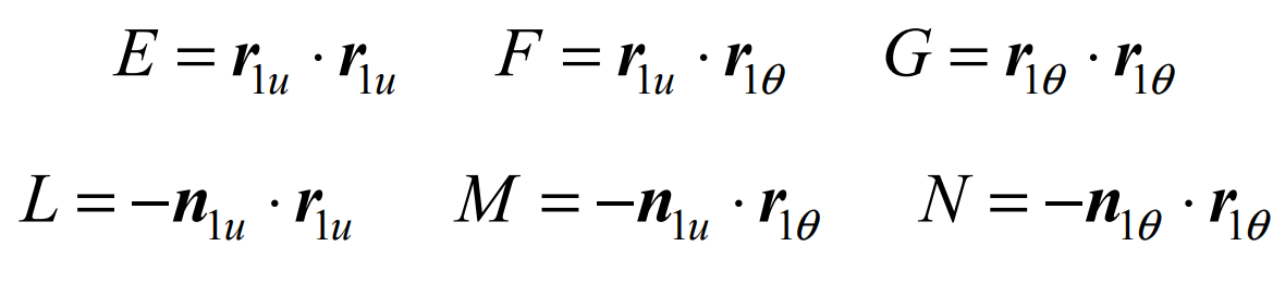
Using the I and II Basic quantities of differential geometry:
The conjugate pinion of spiral bevel gear can be easily obtained by Rodriguez theorem Σ 1 calculate the principal direction and principal curvature of point m as: