
Due to the complexity of face gear tooth surface, it is very difficult to create a complete helical gear model by direct construction method. In order to ensure the accurate tooth surface of helical gear, the geometric modeling of helical gear is carried out by using the same modeling idea as that of spur gear.
It is known from the tooth surface equation of helical gear that there are three independent unknown parameters in the equation ξ s 、 θ S and ϕ s. By controlling the value range of any two parameters and combining with the meshing equation, the data lattice on the tooth surface of helical gear can be obtained. In order to obtain the data lattice along the tooth height direction and tooth width direction of the helical gear, so as to form the helical gear tooth surface, so as to give the value of IX in the tooth surface equation of the helical gear (Xi must be taken between undercutting and tooth tip sharpening). Namely:
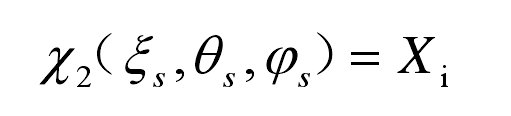
Where IX (I = 1,2,3… N).
According to the meshing boundary conditions of helical gear tooth surface and meshing equation, the parameters are solved ξ S and parameters ϕ Take J discrete points for the value range of S. Then J discrete points are substituted into the tooth surface equation of helical gear, and j Y2 and j Z2 are obtained. Therefore, all coordinate points on the working tooth surface are obtained.
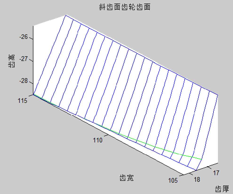
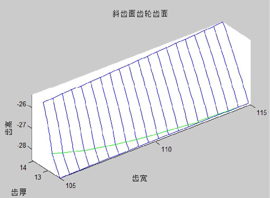
The transition surface of helical gear is solved by the same method. Given the value of ‘IX, combined with the meshing boundary conditions and meshing equation of the tooth root transition surface, the corresponding parameters are obtained, and the discrete point coordinates of the transition surface are solved, so as to obtain the data lattice on the transition surface, so as to obtain the data lattice on the whole tooth surface of the helical gear. As shown in Figure 1, the numerical tooth surfaces on both sides of helical gear are obtained by writing the corresponding matlab program.
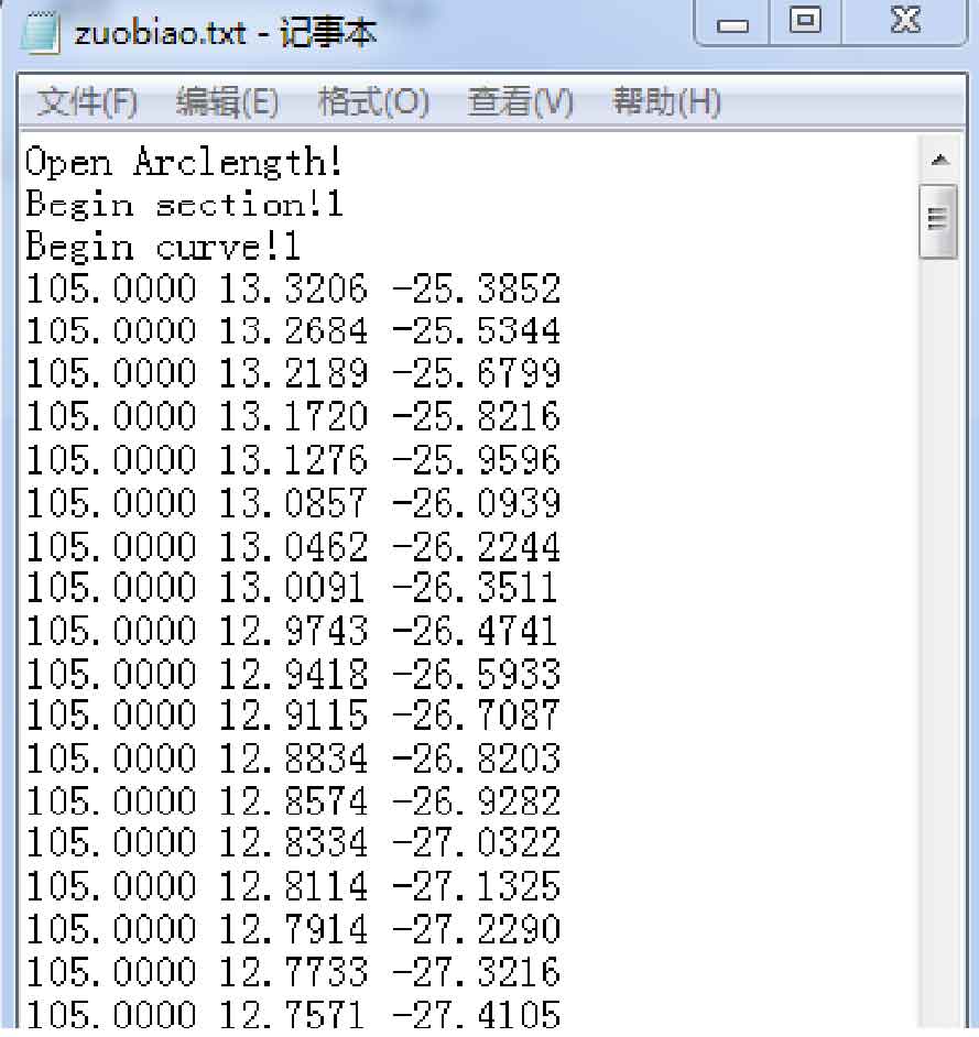
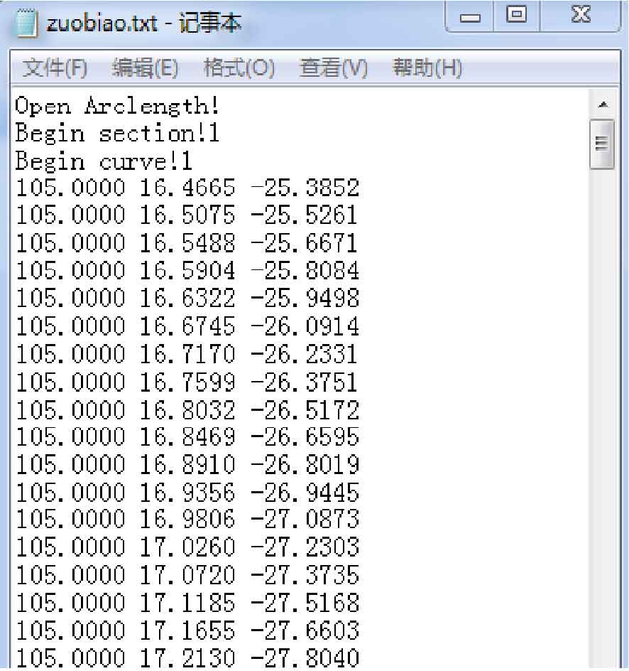
In this paper, a series of discrete point coordinates obtained in MATLAB are input into the file with suffix name of. TXT, and the statement segments readable by Pro / E software are written in the open file, and then the suffix name of the file is changed to. IBL. The purpose is to read out the coordinates of a series of data points obtained in Matlab environment in Pro / E software environment. Then the geometric modeling of helical gear is carried out by using the results of data analysis in Pro / E. Fig. 2 is the coordinates of some dispersion points on the tooth surfaces on both sides of the helical gear.