
As shown in Fig. 1, spur gear shape grinding is to trim the wheel shape to the desired profile and grind it in the groove of the gear being processed to obtain the desired profile of the gear surface.In this paper, a study is carried out on the gears that produce standard involute profiles. Therefore, the grinding wheel used has a standard involute profile.
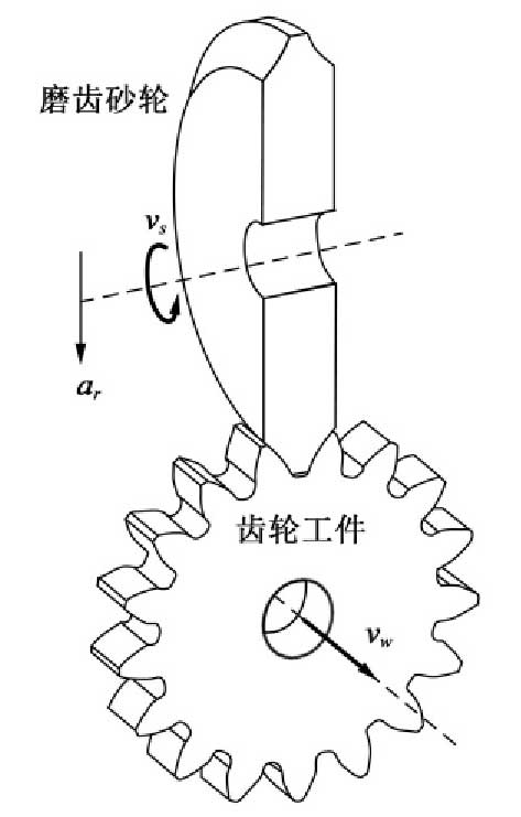
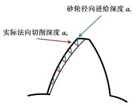
During the forming grinding process, the grinding wheel rotates at the speed V and feeds the AR radially with respect to the gear wheel, and finally moves at the speed V W along the direction of tooth width.The feed direction of the grinding wheel is the gear radial and the radial feed depth is the same at each position on the involute. However, since the involute is a curve, the normal grinding cut depths are different at different positions on the entire involute, as shown in Figure 2.
The Cartesian coordinate system is established with the center of the base circle as the origin, and the involute parameter equation of the radius RB of the base circle is obtained as follows:
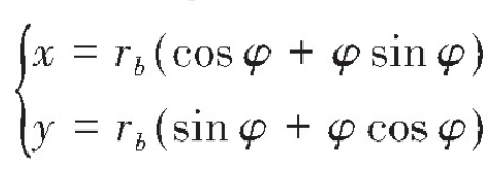
In this formula, the angle between the tangent point of the occurrence line and the base circle and the line connecting the center of the circle and the x-axis is phi.
The established involute equation is transformed to the actual position of the forming grinding process by means of coordinates.
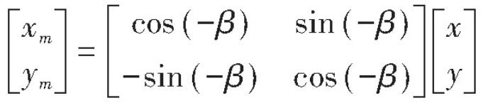
Where beta is half of the corresponding center angle of the base circular pitch.
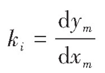
By differentiating the involute equation in Cartesian coordinate system, the slope at a position I is obtained.
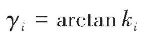
The normal line at this point can be obtained from the slope of a point on the involute, and it can be concluded that the angle gamma I between the radial and normal cut depths of the form grinding at this point is
From this, it can be found that the normal grinding depth at any position on the involute is
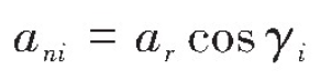
Where ani is the normal grinding depth at any position on the involute and AR is the radial feed depth of the grinding wheel.
Since the contact between the tooth surface and the grinding wheel is not flat in the form grinding, the different locations of the tooth surface have different distances from the center of the grinding wheel spindle, so the grinding line speeds are different in different locations on the involute.
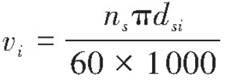
Where VI is the grinding line speed at different locations on the involute, ns is the grinding wheel speed, and DSI is the distance from different locations on the involute to the center of the base circle.