
For the design of general hypoid gear, AGMA standard requires that the transmission conditions of hypoid gear pair must be met: that is, the axes of two pitch cones are staggered (the intersection angle is generally designed to be 90 °), the shortest distance between the two intersection axes of large and small wheels is equal to the designed offset distance of small wheels, and the two pitch cones are tangent to the designed node, The relative motion direction of the node needs to point to the axis direction of the instantaneous spiral motion of the node cone. In addition, when designing a pair of hypoid gears with small number of teeth and large reduction ratio, the first is to limit the number of teeth of the small wheel to no less than 5, and the sum of teeth of the small wheel and the large wheel of the hypoid gear should not be less than 40. Beyond the scope of this design, Gleason’s calculation program will not be able to carry out design and calculation.
When the number of teeth of hypoid gear is reduced by less than 5, in addition to meeting the above meshing conditions, the factors that must be considered are: undercutting, sharpening of tooth top, minimum tool top distance, meshing interference, etc. At this time, the mid point helix angle of the small wheel can be estimated according to the following formula:
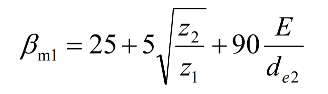
According to the requirements of geometric design of hypoid gear and the limiting conditions of meshing transmission, the value of helix angle of small gear can be adjusted appropriately. Generally, the difference between the helix angle of the designed small wheel and the result calculated by the above formula is no more than 5 °, otherwise it is difficult to meet the strength requirements of hypoid gear.
(1) Minimum teeth limit for undercutting
According to the equivalent number of teeth of hypoid gear pinion, the relationship between the minimum number of teeth and helix angle is preliminarily determined. Considering that the pitch cone angle of the small wheel is small (< 10 °) when the transmission ratio is large, the relationship between the equivalent number of teeth of the hypoid gear small wheel and the helix angle can be approximately as follows:
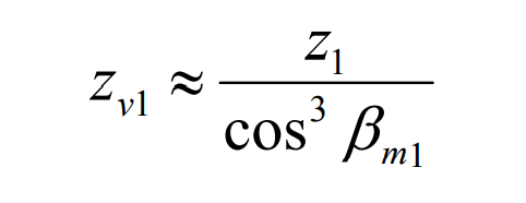
It can be seen from the above formula that selecting a larger helix angle by aligning the hypoid gear small wheel can increase the equivalent number of teeth of the small wheel, so as to avoid the risk of undercutting the small wheel. The number of equivalent teeth of the small wheel shall generally not be less than 20 teeth. Of course, we have to go through the root cutting test in the end.
(2) Limitation of tooth top width of hypoid gear
The tooth tip width of hypoid gear pinion is affected by radial and tangential displacement coefficients. The large wheel of hypoid gear with small number of teeth and large reduction ratio is processed by forming method, so the tooth top width of hypoid gear small wheel can be adjusted by the tool top distance of fine cutting. The calculation formula of tool tip distance W2 of large wheel is:
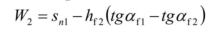
Where, SN1 – the normal spiral tooth thickness of the small wheel node; Hf2 – tooth root height of large wheel; α F1 – pressure angle of convex surface of large wheel and concave surface of small wheel; α F2 pressure angle of concave surface of large wheel and convex surface of small wheel.
The calculation formula of tooth tip width of hypoid gear pinion is:
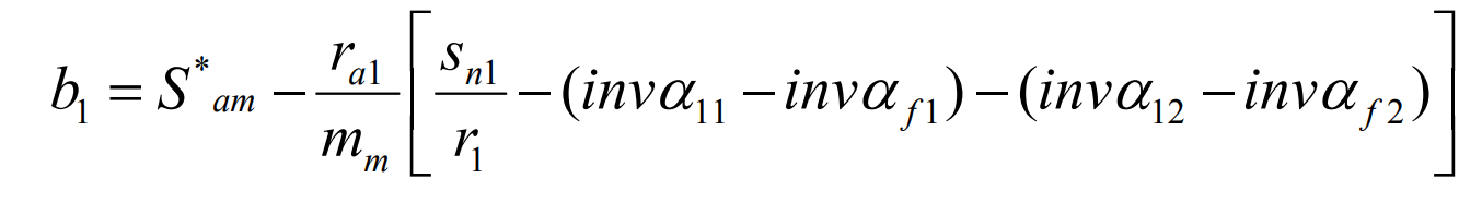
Where, ra1 – radius of tooth tip circle of small wheel; Mm – modulus of center point of small wheel; α 11 – tooth top pressure angle of small wheel concave surface; α 12 – pressure angle of convex surface of small wheel; R1 – radius of indexing circle of small wheel; S * am – allowable end tooth tip thickness coefficient of small wheel.
W2 in the formula and B1 in the formula shall not be less than 0.4 times of the midpoint normal modulus, i.e. 0.4mn.
(3) Limitation of minimum tooth width of hypoid gear
In order to ensure good cutting conditions during hypoid gear processing, the minimum tooth bottom groove width at the inner end of the small wheel should be limited to avoid being too small, which will make it difficult to manufacture cutting tools and cut teeth. This value is also generally limited to 0.4mn. The calculation formula is:
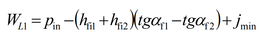
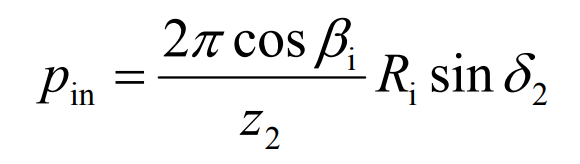
Where, pin is the normal circumferential node at the inner end; Jmin – normal lateral clearance.
The calculation formula of pin is:
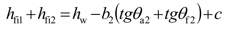
The sum of tooth root heights of large and small gears of hypoid gear is:
(4) Limitation of cone angle of large wheel surface
When the transmission ratio is large, the face cone angle of the big wheel also increases, and the risk of interference between the face cone of the big wheel and the cutter head plane increases. Therefore, the face cone angle of the big wheel should be limited within 85 °.
In addition to the above conditions, it is also necessary to improve the tooth profile through radial displacement and balance the strength of large and small wheels through tangential displacement. Through the comprehensive application of these conditions, the tooth profile variation of hypoid gear in transmission with small number of teeth and large reduction ratio can be completely eliminated. Finally, verify the undercutting and stress of the gear to ensure that the gear working face is affected by the pushing force.