
The demand for compact, high-performance power transmission systems has grown significantly in fields such as aerospace, medical robotics, and precision instrumentation. Among various speed reducer types, the Rotary Vector Reducer (RV Reducer) is renowned for its high torsional rigidity, substantial load capacity, compact size, and excellent positioning accuracy. Traditionally, commercial RV reducers, while highly efficient, often possess a radial dimension exceeding 100 mm, making them unsuitable for applications with stringent space and weight constraints. This gap in the market motivates the research and development of a miniaturized Rotary Vector Reducer. This article presents the comprehensive design process for a small-sized RV reducer, focusing on geometric parameter determination, structural analysis, static force calculation, and strength verification through both theoretical and finite element methods. The primary objective is to validate the feasibility and structural integrity of the proposed compact design.
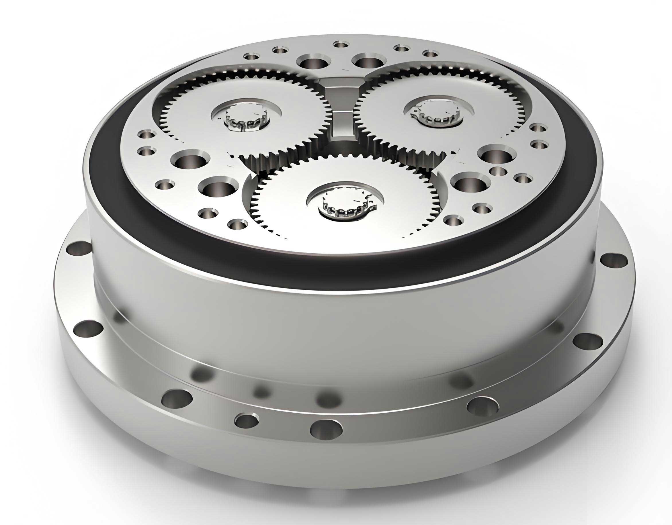
The core architecture of a Rotary Vector Reducer integrates a two-stage speed reduction mechanism into a highly compact housing. The first stage consists of a standard involute planetary gear train, which provides an initial speed reduction. The second stage is a cycloidal-pin gear mechanism, which offers the primary high-ratio reduction and is responsible for the reducer’s high load-bearing characteristics and smooth operation. The output motion is transmitted through a crank mechanism connected to the cycloid disc. For a miniaturized version, every component must be meticulously scaled while maintaining robust performance. The schematic kinematic diagram illustrates this power flow: the input sun gear drives multiple planetary gears, which are mounted on eccentric shafts. These eccentric shafts cause the cycloid discs to undergo a compound eccentric motion relative to the stationary pin gear housing. This eccentric motion is then converted into a slow rotational output via pins (or rollers) connecting the cycloid discs to the output flange. The entire system forms a closed differential gear train, ensuring motion synchronization and high stiffness.
Geometric Parameter Design Methodology
The design of a compact Rotary Vector Reducer begins with defining its core performance specifications. For this study, the target parameters are set as follows: an input power of 0.15 kW, an output speed of 15 rpm, a total reduction ratio of 61, and a maximum outer diameter constraint of approximately 70 mm. The expected output torque \(T_{out}\) can be calculated considering the overall transmission efficiency \(\eta\).
$$T_{out} = 9550 \times \frac{P}{n_{in}} \times i_{RV} \times \eta$$
The overall efficiency \(\eta\) of an RV reducer is a product of the efficiencies of its sub-components, including the involute gear pair \(\eta_{12}\), the cycloid-pin gear pair \(\eta_{bg}\), and various bearing sets \(\eta_{ri}\). Based on empirical values, an estimated efficiency of 0.929 is used, yielding a design output torque \(T_{out} \approx 88.75 \text{ N·m}\).
First-Stage Involute Planetary Gear Design
The first-stage planetary gear set must provide a portion of the total reduction while fitting within the radial envelope. Key constraints for the involute gear design include achieving balanced tooth wear, ensuring proper meshing without interference, and aligning its radial dimensions with the subsequent cycloid stage. The gear parameters are selected under the following principles:
- The tooth numbers should satisfy the desired stage ratio. To prevent excessive torque on the planetary pins, the ratio of planetary gear teeth \(z_2\) to sun gear teeth \(z_1\) should be \(z_2 / z_1 \geq 1.5\).
- The sun gear, being the smallest, should have a sufficient number of teeth to avoid undercutting and ensure smooth operation, typically within \(9 \leq z_1 \leq 20\).
- To maintain compactness and force balance, the center distance \(a\) of the planetary stage should be proportional to the pitch radius \(r_p\) of the cycloid pin circle: \(a = (0.5 \sim 0.6) r_p\).
- The radial size of the planetary stage should be comparable to the cycloid stage: \(m(z_1/2 + z_2) = (0.9 \sim 1.1) r_p\).
- To avoid interference between adjacent planetary gears, their tip diameter \(d_{a2}\) must satisfy: \(d_{a2} < 2a \sin(\pi / n_w)\), where \(n_w\) is the number of planets.
Given the high reduction ratio requirement and size limit, a sun gear with \(z_1 = 15\) and planetary gears with \(z_2 = 30\) are chosen, providing a first-stage ratio of 3 (\(i_1 = 1 + z_2/z_1\)). Three planetary gears (\(n_w=3\)) are used for force balance. To equalize sliding wear and improve strength, profile shifting (modification) is applied. The sun gear is given a positive shift coefficient \(x_1\) and the planets a negative one \(x_2\), determined by equating their maximum sliding coefficients \(\eta_{max}\). The basic geometric parameters for this miniaturized Rotary Vector Reducer’s first stage are summarized in Table 1.
| Parameter | Symbol | Value |
|---|---|---|
| Module | \(m\) | 0.5 mm |
| Sun Gear Teeth | \(z_1\) | 15 |
| Planetary Gear Teeth | \(z_2\) | 30 |
| Number of Planets | \(n_w\) | 3 |
| Pressure Angle | \(\alpha\) | 20° |
| Sun Gear Shift Coefficient | \(x_1\) | +0.34 |
| Planetary Gear Shift Coefficient | \(x_2\) | -0.34 |
| Center Distance | \(a\) | 11.25 mm |
| Contact Ratio | \(\varepsilon_{\alpha}\) | 1.512 |
Second-Stage Cycloid-Pin Gear Design
The cycloid-pin gear pair is the heart of the Rotary Vector Reducer, providing the main speed reduction and high torque capacity. Its design is governed by specific geometric relationships to ensure proper meshing, avoid tooth undercutting, and achieve the desired reduction ratio \(i_2\). The total RV ratio is given by \(i_{RV} = i_1 \times i_2\), where \(i_2 = z_b / (z_b – z_g)\). Here, \(z_b\) is the number of pin teeth (stationary) and \(z_g\) is the number of cycloid disc teeth. With \(i_{RV}=61\) and \(i_1=3\), we get \(i_2 \approx 20.33\). Selecting \(z_b = 30\) and \(z_g = 29\) satisfies this requirement.
The primary design parameters include the pin circle radius \(r_p\), the pin radius \(r_{rp}\), the eccentricity \(e\) of the crankshaft, and the shortening coefficient \(K_1\). The eccentricity is fundamentally related to these parameters: \(e = K_1 r_p / z_b\). The shortening coefficient \(K_1\), typically between 0.5 and 1.0, critically influences the force distribution and contact stress. A value of \(K_1 = 0.675\) is chosen as a starting point. To prevent undercutting of the cycloid tooth profile, the minimum curvature radius \(\rho_{0min}\) of the theoretical cycloid must be greater than the pin radius \(r_{rp}\). The minimum curvature radius is given by:
$$\rho_{0min} = -r_p \cdot a_{min} \quad \text{where} \quad a_{min} = \frac{27 z_g^3 (1 – K_1^2)}{(z_g + 2)^3}$$
The condition \(\rho_{0min} > r_{rp}\) must be checked. Furthermore, to ensure adequate strength of the pin gear housing, a pin diameter coefficient \(K_2\) is defined and should be maintained within \(1.5 \le K_2 \le 2.0\):
$$K_2 = \frac{r_p \sin(\pi / z_b)}{r_{rp}}$$
Setting \(r_p = 20\) mm and iteratively solving the geometric constraints leads to the final parameters listed in Table 2 for this compact Rotary Vector Reducer’s cycloid stage.
| Parameter | Symbol | Value |
|---|---|---|
| Pin Circle Radius | \(r_p\) | 20.0 mm |
| Pin Radius | \(r_{rp}\) | 1.3 mm |
| Number of Pin Teeth | \(z_b\) | 30 |
| Number of Cycloid Teeth | \(z_g\) | 29 |
| Eccentricity | \(e\) | 0.45 mm |
| Shortening Coefficient | \(K_1\) | 0.675 |
| Pin Diameter Coefficient | \(K_2\) | 1.608 |
Output Mechanism and Bearing Selection
The output mechanism, typically a pin-in-hole or roller-in-slot design, converts the eccentric motion of the cycloid disc into rotary output. For this small-sized Rotary Vector Reducer, a pin (or roller) mechanism is employed. The diameter of the output pins \(d_w\) and the diameter of their corresponding holes in the cycloid disc \(d_{gw}\) are related by the eccentricity: \(d_{gw} = d_w + 2e\). The distribution of these holes must ensure sufficient material strength between them and between the holes and the central bore of the cycloid disc. The wall thickness \(\delta\) between adjacent holes should satisfy \(\delta \ge 0.03 r_p\).
Bearing selection is critical in a miniaturized Rotary Vector Reducer due to space constraints. The eccentric shafts require compact yet robust bearings to support the cycloid discs. Instead of the traditional needle roller bearings, micro-ball bearings (e.g., MR95zz, MR104zz series) are specified. Their integrated inner and outer races simplify assembly and contribute to the overall compactness of the reducer design. The width of the cycloid disc is set equal to the width of these selected micro-bearings.
Force Analysis and Theoretical Strength Verification
To ensure the structural integrity of the designed compact Rotary Vector Reducer, a thorough force analysis and strength check for both gear stages is imperative. The materials selected are 20CrMnTi for the involute gears and GCr15 bearing steel for the cycloid-pin gear components.
Forces on the Involute Planetary Stage
Assuming negligible friction, the tangential force \(F_t\) between the sun gear and a single planetary gear is calculated from the input torque \(T_{in}\). The radial force \(F_r\) is derived from the pressure angle.
$$F_{t21} = \frac{2 T_{in}}{n_w \cdot d_1}, \quad F_{r21} = F_{t21} \cdot \tan(\alpha’)$$
Where \(F_{t21}\) is the force from the sun gear (2) acting on the planetary gear (1), \(d_1\) is the pitch diameter of the sun gear, and \(\alpha’\) is the operating pressure angle. For the given input power and speed (\(T_{in} \approx 0.955 \text{ N·m}\)), the calculated forces are: \(F_t \approx 208.74 \text{ N}\) and \(F_r \approx 75.98 \text{ N}\).
Forces on the Cycloid-Pin Stage
The force analysis for the cycloid gear is more complex due to the multi-tooth contact nature of the cycloidal drive. Not all pin teeth are in load-bearing contact simultaneously. The resultant force from the pins acts through the instantaneous center of motion. Based on torque equilibrium and assuming a sinusoidal load distribution among the engaged teeth, the maximum force on a single cycloid tooth \(F_{max}\) can be approximated. Considering a load distribution factor of 0.55 for the torque shared by a single cycloid disc, the formula is:
$$F_{max} = \frac{2.2 \cdot T_{out}}{r_p \cdot K_1 \cdot z_g}$$
Substituting the values yields \(F_{max} \approx 498.72 \text{ N}\). This force is used for contact stress calculation.
Theoretical Strength Check
Involute Gear Strength: The sun and planetary gears are checked for bending stress \(\sigma_F\) and contact stress \(\sigma_H\) using standard AGMA-inspired formulas. The bending stress is calculated as:
$$\sigma_F = \frac{K_F F_t Y_{Fa} Y_{Sa} Y_{\epsilon}}{m b}$$
And the contact stress as:
$$\sigma_H = \sqrt{ \frac{2 K_H T_1}{b d_1^2} \cdot \frac{u+1}{u} } \cdot Z_H Z_E Z_{\epsilon}$$
Where \(K_F, K_H\) are application factors, \(Y_{Fa}, Y_{Sa}\) are tooth form and stress correction factors, \(Z_H, Z_E\) are zone and elasticity factors, \(b\) is face width, and \(u\) is gear ratio. The calculated stresses must be below the allowable stresses \([\sigma_F]\) and \([\sigma_H]\) for the chosen material (20CrMnTi, case-hardened).
Cycloid-Pin Contact Strength: The contact between the cycloid disc and a pin is modeled as contact between two cylinders. The maximum contact stress \(\sigma_{H2}\) is calculated using the Hertzian contact formula:
$$\sigma_{H2} = 0.418 \sqrt{ \frac{F_{max}}{B \rho_d} \cdot \frac{2 E_1 E_2}{E_1 + E_2} }$$
Here, \(B\) is the cycloid disc width, \(E_1, E_2\) are the elastic moduli of the cycloid disc and pin materials (both GCr15, ~206 GPa), and \(\rho_d\) is the equivalent radius of curvature. The equivalent curvature \(1/\rho_d\) is found from the instantaneous geometry of the cycloid profile and the pin:
$$\frac{1}{\rho_d} = \frac{1}{r_{rp}} – \frac{1}{\rho} = \frac{\rho_0}{r_{rp}(\rho_0 + r_{rp})}$$
Where \(\rho_0\) is the theoretical cycloid profile’s curvature radius at the point of maximum force. The calculated contact stress must be below the allowable contact stress for GCr15.
The results of the theoretical strength calculations are consolidated in Table 3. Both stages show safety factors well above 1, indicating the design is theoretically sound from a static strength perspective for this small-scale Rotary Vector Reducer.
| Component | Stress Type | Calculated Value (MPa) | Allowable Value (MPa) | Safety Status |
|---|---|---|---|---|
| Involute Gears | Bending Stress \(\sigma_F\) | 697.8 (Sun), 667.5 (Planet) | 720 | Safe |
| Contact Stress \(\sigma_H\) | 664.9 | 1260 | Safe | |
| Cycloid-Pin Pair | Contact Stress \(\sigma_{H2}\) | 263.8 | 1300 | Safe |
Finite Element Analysis (FEA) and Validation
To complement the theoretical analysis and validate the design under more realistic conditions, Finite Element Analysis (FEA) was conducted on the two critical gear pairs of the compact Rotary Vector Reducer. High-fidelity 3D models were created based on the parameters in Tables 1 and 2.
FEA of the Involute Planetary Gear Pair
A single sun-planet gear pair was analyzed to reduce computational cost. The model was meshed with a fine tetrahedral mesh, particularly refined at the contact regions. Material properties for 20CrMnTi (E = 207 GPa, ν = 0.254) were assigned. A frictional contact (μ=0.1) was defined between the gear teeth. The sun gear’s inner surface was coupled to a reference point where the input torque (782.78 N·mm) was applied. The planetary gear’s inner hole was constrained to only rotate about its axis. The analysis solved for deformation, von Mises stress, and contact pressure.
The FEA results showed a maximum total deformation of 0.1257 mm. The maximum von Mises stress was 693.0 MPa, located at the root fillet of the sun gear tooth. Most importantly, the maximum contact stress on the tooth flank was found to be 703.3 MPa.
FEA of the Cycloid-Pin Gear Pair
For the cycloid stage, a sector model containing the cycloid disc engaged with several pins was analyzed to leverage symmetry and reduce model size. The pins and their housing were modeled as a single rigid component fixed in space. The cycloid disc material was set as GCr15 (E = 206 GPa, ν = 0.3). A frictionless contact was defined between the cycloid tooth flanks and the pins. A cylindrical support was applied to the cycloid disc’s inner bore, allowing only rotation. The design torque for a single disc (1479.7 N·mm) was applied to this bore.
The results indicated a very small maximum total deformation of 0.00121 mm. The maximum von Mises stress was 276.7 MPa. The maximum contact stress extracted from the solution was 234.7 MPa.
Comparison of Theoretical and FEA Results
A direct comparison between the theoretical calculations and the FEA simulations provides crucial validation for the design methodology of the miniaturized Rotary Vector Reducer. The key metric for comparison is the maximum contact stress, as it is most directly comparable between the analytical Hertzian theory and the FEA contact algorithm. The results are summarized in Table 4.
| Gear Pair | Theoretical Value \(\sigma_{H}\) (MPa) | FEA Value \(\sigma_{H}\) (MPa) | Allowable Stress \([\sigma_{H}]\) (MPa) | Relative Error |
|---|---|---|---|---|
| Involute Stage | 664.9 | 703.3 | 1260 | 5.77% |
| Cycloid-Pin Stage | 263.8 | 234.7 | 1300 | -11.03% |
The discrepancies are within an acceptable engineering margin. The 5.77% higher FEA contact stress for the involute gears can be attributed to stress concentrations at the edges of the contact zone, which are idealized in the theoretical formula. The 11.03% lower FEA stress for the cycloid pair is likely due to the simplified theoretical model assuming a worst-case point load, whereas the FEA captures a more distributed load sharing among multiple teeth. In both cases, the stresses are significantly below the material’s allowable limits, confirming the structural integrity and safety of the proposed design for a compact Rotary Vector Reducer.
Conclusion
This work has detailed the complete design and analysis process for a novel small-sized Rotary Vector Reducer with a target outer diameter under 70 mm. By systematically applying geometric constraints for miniaturization, the key parameters for both the involute planetary stage and the cycloid-pin stage were determined. A comprehensive force analysis and theoretical strength check were performed, confirming that the stresses in all critical components are within safe limits for the chosen materials.
The design was further validated through detailed Finite Element Analysis. The close correlation between the theoretical contact stress calculations and the FEA simulation results, with errors of 5.77% for the involute gears and 11.03% for the cycloid-pin pair, strongly verifies the correctness of the analytical models and the fundamental soundness of the geometric design. The successful integration of micro-bearings and a carefully sized output pin mechanism demonstrates the feasibility of achieving the required functionality within a drastically reduced footprint.
This study provides a solid theoretical foundation and a validated design framework for the development of compact Rotary Vector Reducers. Future work will focus on dynamic analysis, efficiency testing, thermal performance, precision manufacturing considerations, and prototyping to fully realize the potential of this miniaturized power transmission solution for advanced applications in robotics and precision machinery.