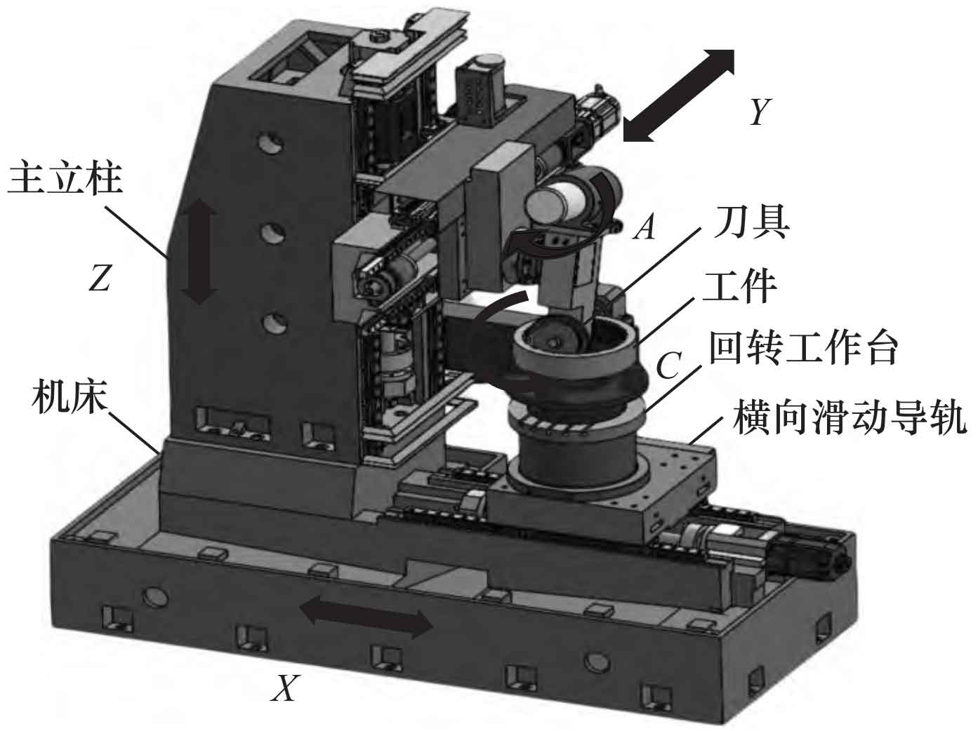
ZHY Gear adopts the principle of a multi-body system and establishes its kinematic model using a CNC machine tool to grind internal helical gears as an example. The CNC formed grinding wheel grinding machine has five linked axes: X, Y, Z, A, and C. Among them, the X, Z, and C axes are the main motion axes of the machine tool grinding system. The X and Z axes are fixed to the machine tool bed, and the C axis is the workpiece indexing CNC rotary table, installed on the X axis; The Y-axis and A-axis assist in motion, while the A-axis is used to control the rotation of the grinding wheel and achieve the machining of the internal helical gear, which is installed on the Z-axis workbench. The schematic diagram of the machine tool motion axis is shown in Figure 1.
1. Multibody System Topology and Low Order Body Arrays
Based on kinematic analysis of the internal helical gear grinding system, the machine tool system is divided into two motion chains. The workpiece motion chain starts from the machine body and ends at the workpiece end, while the tool motion chain starts from the machine body and ends at the tool end. The two determine the adjacent low order body relationship of each moving component, and number the motion axes based on the motion relationship. The topology diagram of the CNC gear grinding machine is shown in Figure 2.
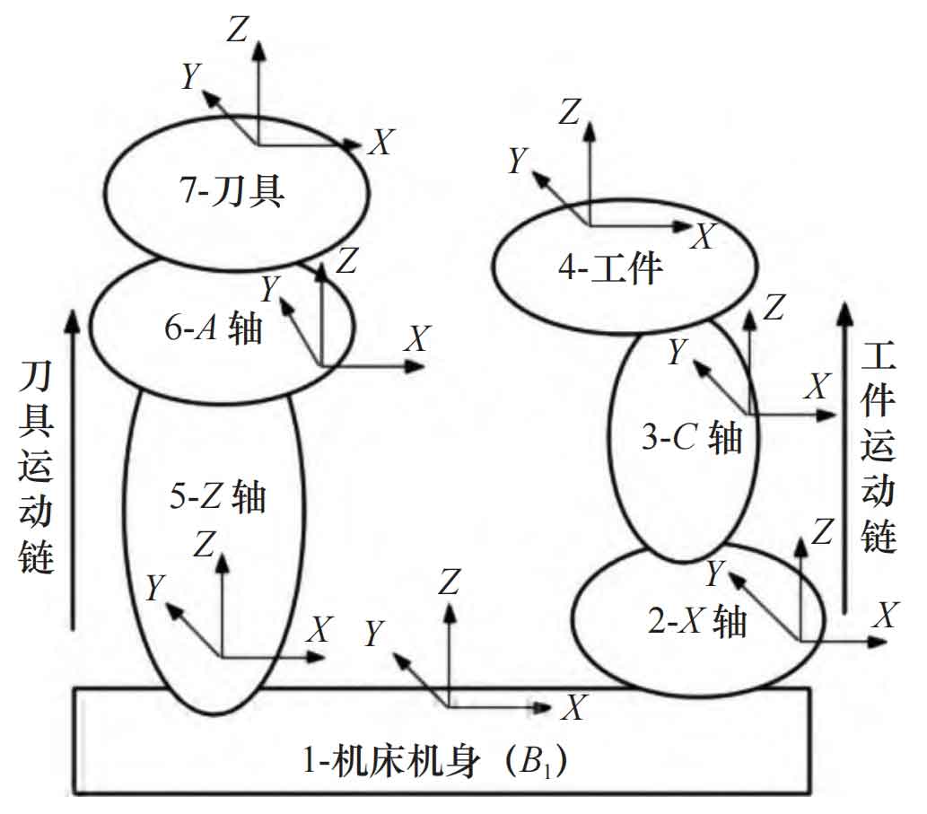
From Figure 2, it can be seen that in the multi-body system, only the B1 moving body is initially labeled, and each other moving body has adjacent numbered moving bodies. By listing the numbering of each moving body in the system, represented by L (K), K is the numbering of the moving body in the system.
Assuming S is an adjacent low order body of K, the relationship between adjacent moving bodies can be expressed using the formula:

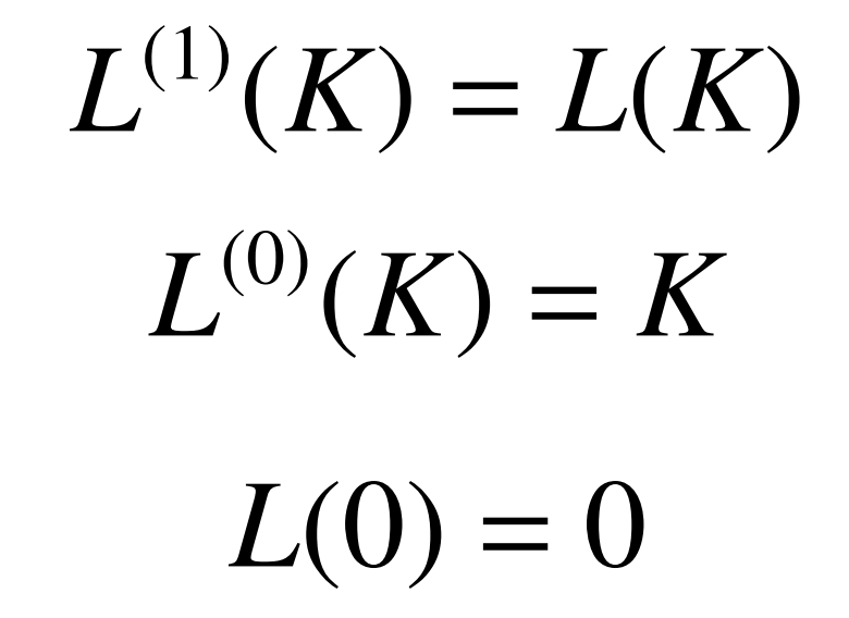
If the low order operator is represented by L, then there are:

The definition of low order operator is:
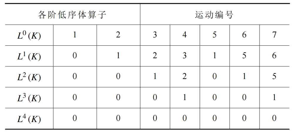
The low order body array of multi-body systems can be obtained through the above formula, as shown in Table 1.
2. Geometric model of machining errors
The sequence of the internal helical gear grinding system from the workpiece to the tool motion chain shown in Figure 2 is: connecting the C-axis of the workpiece to the X-axis of the machine body, and then connecting the Z-axis of the machine body to the A-axis until the end of the tool. Therefore, the ideal state coordinate transformation relationship matrix between the coordinate systems of each moving body in the motion chain of the internal helical gear grinding system is as follows: TgC, TCX, TXJ, TJZ, TZA, TAW.
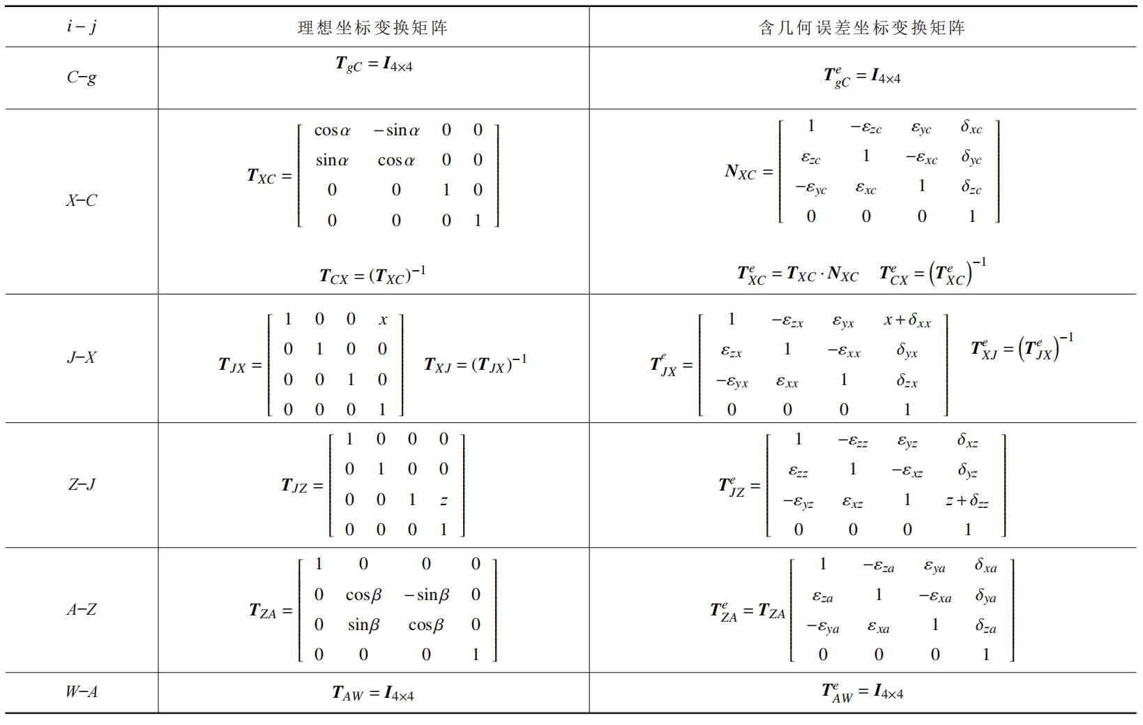
From the coordinate transformation matrix in Table 2, the homogeneous coordinate transformation matrix TgW between the tool and the workpiece in the ideal state of the multi body system for grinding internal helical gears can be obtained, namely:

Due to geometric errors in the motion axes of the machine tool during the grinding of internal helical gears, it is also necessary to calculate the homogeneous coordinate transformation matrix between the tool and the internal helical gear in the presence of errors. In the presence of errors, the transformation matrix is:

The error matrix between the tool and the workpiece coordinate system in the construction of the helical gear grinding system in the machine tool is EgW. In the case of error, the transformation matrix TegW between the two coordinate systems is equal to the product of the error matrix EgW and the ideal transformation matrix TgW between the two coordinate systems, that is:

So:

By assuming the minimum error, EgW is expressed as:
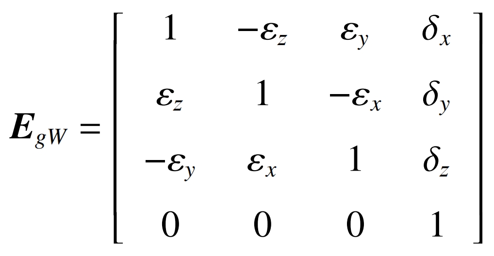
In the formula: δ X δ Y δ Z represents the displacement components of geometric errors in the X, Y, and Z directions, respectively, ε X ε Y ε Z represents the angular components of geometric errors in the X, Y, and Z directions, respectively.
3. Tooth surface error model
In the process of grinding, if the dressing error of the grinding wheel is ignored to represent the axial profile parameters of the grinding wheel, the coordinate vector of the corrected axial profile of the grinding wheel is:

The rotational surface of a grinding wheel is a trajectory surface formed by its axial profile rotating around an axis. The rotation parameters of the grinding wheel are represented by, and in the coordinate system of the grinding wheel, its coordinate vector is:
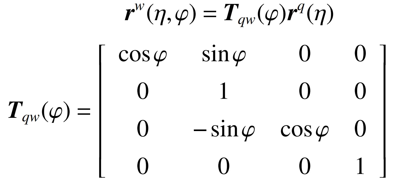
The normal vector of the grinding wheel unit is:
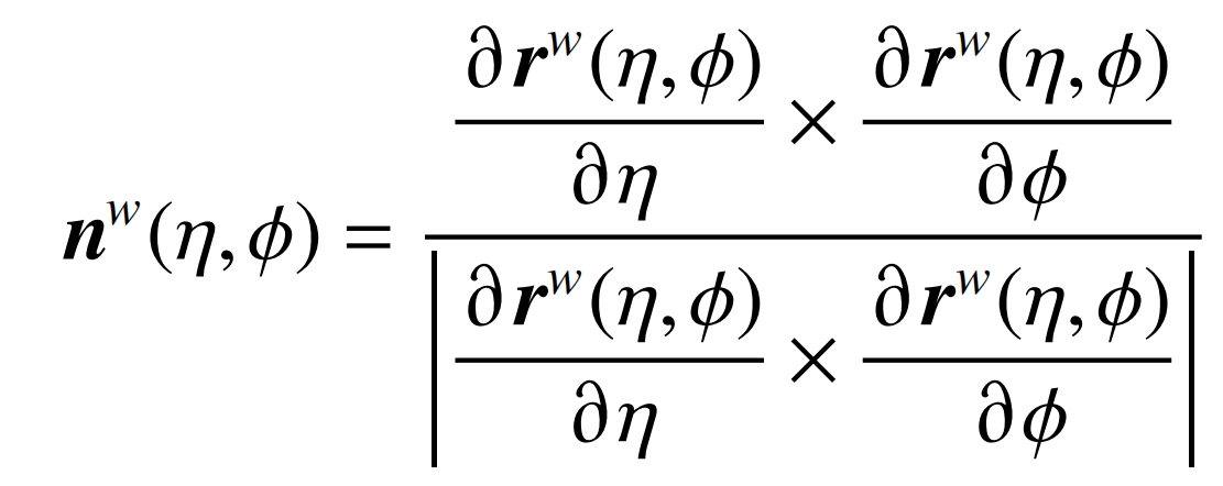
Due to the fact that the surface features of grinding wheels can be represented by a combination of unit normal vectors and coordinate vectors, the ideal grinding wheel surface in a helical gear coordinate system can be represented as:

In actual machining, the geometric errors of each axis are represented by the vector G=[x1, x2, ····, xm] ^ T, so the actual grinding wheel surface is:

The condition for the contact point between the grinding wheel and the helical gear during grinding is to make a radial vector from the origin of the helical gear coordinate system towards the grinding wheel rotation surface. If the normal of this point on the rotation surface is perpendicular to the linear velocity vector around the helical gear axis, it indicates that this point is the grinding contact point. Therefore, the ideal contact conditions and the actual contact conditions are:

In the formula: β Is the installation angle of the grinding wheel, constant; Is the center distance from the grinding wheel to the helical gear, constant; α It is a spiral machining parameter that only affects the shape of the contact line when geometric errors exist, and the geometric error vector G is only related to the position of each motion axis. When α When f=0 is a constant, it becomes only related to the axial and rotational profile parameters of the grinding wheel as a contact condition. Due to the known range of its axial profile, it will be divided into n discrete values, and the corresponding values will be calculated based on f=0. Then, the unit formula and coordinate vector of the contact point can be obtained by substituting it in. Due to the joint calculation with f=0, the function can be used to represent, and the th contact line fitted by contact points can also be represented as:
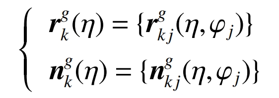
And the helical gear tooth surface can be seen as composed of λ The ideal and actual helical gear tooth surfaces are represented as:
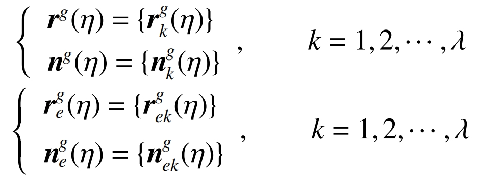
Therefore, the relationship between geometric errors of each axis and helical gear tooth surface errors can be established, and the model is:

