
The pursuit of enhanced mechanical performance and extended service life for critical components is a constant driver in mechanical engineering. Among these components, spur and pinion gears are fundamental, transmitting power and motion in countless applications from automotive transmissions to industrial machinery. Their performance is critically dependent on achieving superior surface hardness, wear resistance, and high resistance to contact and bending fatigue. These properties are imparted not just by the material selection but, more decisively, by the final heat treatment process, with quenching being the most pivotal and complex stage. Quenching involves rapid cooling from an austenitizing temperature to induce a hard martensitic microstructure. However, the intense thermal gradients generated during this rapid cooling can lead to undesirable distortions, residual stresses, and even cracking, jeopardizing the very performance the process aims to enhance.
Traditional liquid quenching media, like oil or water, offer high cooling intensities but often at the cost of severe thermal shock and poor control over the cooling profile. In recent years, atomized gas quenching has emerged as a promising alternative technology. This process utilizes a mixture of a gas (typically nitrogen or inert gases) and a fine mist of liquid (often water) sprayed onto the hot workpiece. The technology offers a unique combination of a high heat transfer coefficient, excellent temperature uniformity across complex geometries, a high critical heat flux density, and lower required flow rates of quenchant compared to pure liquid immersion. For a complex component like a spur and pinion gear, achieving uniform cooling is particularly challenging due to its varied cross-sections—thin teeth and a thicker web or hub. Non-uniform cooling can result in uneven hardness and significant distortion. Therefore, accurately predicting the temperature evolution during the quenching of a spur and pinion gear is the first and most crucial step in assessing the final metallurgical outcome and the resulting stress state.
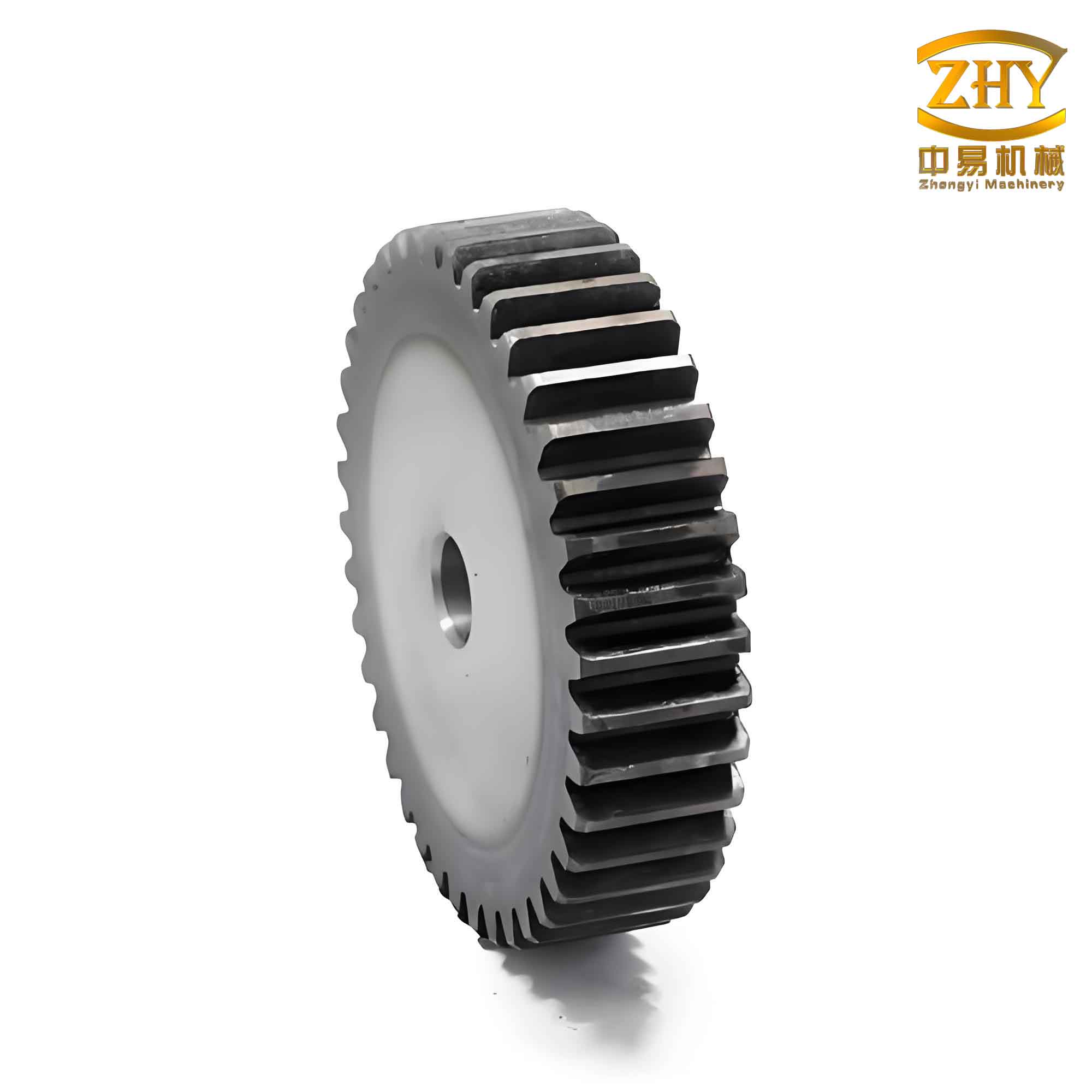
This article presents a comprehensive numerical and experimental investigation into the transient heat transfer during the atomized gas quenching of a spur and pinion gear. We will develop a robust simulation framework that accurately captures the physics of the process. The core of this framework is the calculation of the surface heat transfer coefficient (HTC), a critical boundary condition that governs the cooling rate. The HTC is not constant; it varies dramatically with surface temperature, transitioning through different boiling regimes. We will calculate this variable HTC using fundamental heat transfer theory implemented in computational software. Subsequently, we will employ Finite Element Analysis (FEA) to solve the three-dimensional, transient heat conduction problem for a spur and pinion gear model, explicitly accounting for the latent heat released during phase transformations. Finally, we will validate our numerical predictions against experimental temperature measurements obtained during the quenching of a physical spur and pinion gear specimen.
Theoretical Foundations of Heat Transfer during Quenching
The cooling of a spur and pinion gear during quenching is governed by the fundamental laws of heat conduction within the solid and convection/radiation at its boundaries. The general form of the transient heat conduction equation with an internal heat source in a three-dimensional Cartesian coordinate system is derived from Fourier’s law and the conservation of energy principle:
$$ \rho(T) c_p(T) \frac{\partial T}{\partial t} = \nabla \cdot (k(T) \nabla T) + \dot{q}_{gen} $$
where:
- $ \rho(T) $ is the temperature-dependent density (kg/m³),
- $ c_p(T) $ is the temperature-dependent specific heat capacity (J/(kg·K)),
- $ T $ is the temperature (K or °C),
- $ t $ is time (s),
- $ k(T) $ is the temperature-dependent thermal conductivity (W/(m·K)),
- $ \dot{q}_{gen} $ is the rate of internal heat generation per unit volume (W/m³).
For a spur and pinion gear, it is often more convenient to use a cylindrical coordinate system $(r, \phi, z)$ due to its rotational symmetry, though the full 3D geometry of the teeth requires a general approach. The primary internal heat source during quenching is the latent heat released during the austenite-to-martensite (and possibly other phases like bainite) transformation. This latent heat $\dot{q}_{latent}$ can be significant and acts as an internal energy source that slows down the cooling rate at the transformation temperature range.
The boundary conditions are crucial for an accurate solution. During atomized gas quenching, all exposed surfaces of the spur and pinion gear exchange heat with the environment. The boundary condition is of the convective/radiative type (Robin condition):
$$ -k \frac{\partial T}{\partial n} \bigg|_{\Gamma} = h_{total}(T_s, t) \left( T_s – T_{\infty} \right) $$
where:
- $ \frac{\partial T}{\partial n} $ is the temperature gradient normal to the surface $\Gamma$,
- $ h_{total}(T_s, t) $ is the total surface heat transfer coefficient, which is a complex function of the surface temperature $T_s$ and potentially time,
- $ T_{\infty} $ is the temperature of the quenching medium (for sprayed surfaces) or the ambient air (for non-sprayed surfaces).
The total HTC, $ h_{total} $, for surfaces exposed to the atomized spray combines the effects of forced convection from the gas and droplets, as well as boiling phenomena (film and nucleate boiling) from the liquid phase. For surfaces not directly impinged by the spray, natural convection and radiation to the surroundings dominate. The functional form of $ h_{total}(T_s) $ is the key to realistic simulation and is the focus of the next section.
Numerical Simulation Methodology
Material Properties and Phase Transformation Latent Heat
We consider a medium-carbon steel, such as AISI 1045 or its equivalent, a common material for high-strength spur and pinion gears. Its thermophysical properties are strongly temperature-dependent, especially across phase transformation ranges. A representative set of data is summarized in the table below.
| Temperature, T (°C) | Density, ρ (kg/m³) | Specific Heat, c_p (J/(kg·K)) | Thermal Conductivity, k (W/(m·K)) |
|---|---|---|---|
| 20 | 7850 | 472 | 47.7 |
| 200 | 7800 | 498 | 40.4 |
| 400 | 7750 | 560 | 36.0 |
| 600 | 7700 | 700 | 32.0 |
| 800 (Austenite) | 7650 | 806 | 26.5 |
| 1000 (Austenite) | 7600 | 602 | 24.0 |
Handling the latent heat of transformation is critical. The most common and effective method within FEA is the enthalpy method or the effective heat capacity method. Instead of treating latent heat as an internal source term $\dot{q}_{gen}$, it is incorporated by modifying the specific heat capacity over the transformation temperature range. The effective specific heat $c_{p,eff}$ is defined as:
$$ c_{p,eff}(T) = c_p(T) + L \frac{df}{dT} $$
where $L$ is the total latent heat per unit mass (J/kg) for the transformation, and $f$ is the volume fraction of the transformed phase (e.g., martensite), which is a function of temperature described by the Koistinen-Marburger equation for martensite or Avrami-type equations for diffusional transformations. The derivative $\frac{df}{dT}$ acts as a peak function over the transformation range, effectively increasing the heat capacity to account for the energy release. This method ensures energy conservation and integrates seamlessly into the standard heat conduction equation.
Finite Element Model of the Spur and Pinion Gear
A 3D solid model of a spur and pinion gear is created, defining key parameters such as module, number of teeth, face width, and hub geometry. This model is then discretized into a finite element mesh. For thermal analysis, a mix of higher-order tetrahedral and hexahedral elements is suitable. The mesh must be sufficiently refined, especially on the tooth flanks and tips where geometry changes rapidly and high thermal gradients are expected. The web or hub region, being thicker, can have a slightly coarser mesh. An initial uniform temperature equal to the austenitizing temperature (e.g., 850°C) is assigned to the entire spur and pinion gear model.
Determination of the Surface Heat Transfer Coefficient (HTC)
The heat extraction capability of the atomized gas spray is encapsulated in the HTC function $h_{total}(T_s)$. For a spray combining liquid and gas, the heat transfer mechanisms evolve through distinct regimes as the surface temperature decreases:
- Film Boiling Regime (Very High $T_s$): At temperatures well above the Leidenfrost point, a stable vapor film blankets the surface. Heat transfer occurs through conduction and radiation across this film, resulting in a relatively low HTC.
- Transition Boiling Regime (High $T_s$): As the surface temperature drops, the vapor film becomes unstable and collapses intermittently, allowing liquid to contact the surface briefly. The HTC increases significantly in this regime.
- Nucleate Boiling Regime (Moderate $T_s$): Below a certain temperature, stable film boiling ceases. Vigorous bubble nucleation and growth at active sites on the surface characterizes this regime, providing the peak HTC.
- Single-Phase Forced Convection (Low $T_s$): When the surface temperature falls below the liquid’s saturation temperature, boiling stops. Heat is removed by forced convection of the gas and liquid droplets, leading to a lower, gradually decreasing HTC.
Modeling this behavior requires empirical or semi-empirical correlations. A piecewise function can be constructed based on established boiling curves and spray cooling correlations. The maximum HTC ($h_{max}$) and the temperature at which it occurs ($T_{max}$) are key parameters influenced by spray variables: liquid flow rate (Water Mass Flux, $G_{w}$), gas pressure/density, droplet velocity and size, and impingement density.
For the spur and pinion gear simulation, we calculate this $h(T_s)$ curve using an inverse method or by applying published correlations for air-mist sprays. The relationship is highly non-linear. A simplified representation of the calculated HTC trend for a typical atomized gas quench condition is shown conceptually by the function below and the subsequent descriptive table.
$$ h_{total}(T_s) = \begin{cases}
h_{film}, & T_s > T_{L} \quad \text{(Film Boiling)} \\
h_{film} + (h_{max}-h_{film})\left(\frac{T_{L}-T_s}{T_{L}-T_{max}}\right)^n, & T_{max} < T_s \leq T_{L} \quad \text{(Transition)} \\
h_{max}, & T_s = T_{max} \quad \text{(Peak)} \\
h_{max} \left(\frac{T_s – T_{sat}}{T_{max} – T_{sat}}\right)^m, & T_{sat} < T_s < T_{max} \quad \text{(Nucleate Boiling)} \\
h_{conv}, & T_s \leq T_{sat} \quad \text{(Forced Convection)}
\end{cases} $$
Where $T_L$ is the Leidenfrost temperature, $T_{max}$ is the temperature at peak HTC, $T_{sat}$ is the saturation temperature of the liquid, and $n, m$ are exponents. The parameters $h_{film}$, $h_{max}$, and $h_{conv}$ are determined from process conditions.
| Regime | Surface Temperature Range | Dominant Mechanism | Approximate HTC Range (W/m²K) |
|---|---|---|---|
| Film Boiling | > 400°C | Conduction/Radiation through vapor film | 200 – 800 |
| Transition Boiling | 250°C – 400°C | Unstable film collapse, intermittent liquid contact | 800 – 5000 |
| Nucleate Boiling | 150°C – 250°C | Vigorous bubble nucleation and growth | 3000 – 15000 (Peak) |
| Forced Convection | < 150°C | Convective cooling by gas and droplets | 500 – 3000 |
This calculated $h_{total}(T_s)$ function is then applied as a boundary condition to all surfaces of the FE model that are exposed to the direct spray. For the bore or other shielded surfaces, a combined natural convection and radiation coefficient (e.g., 10-20 W/m²K) is applied.
Simulation Results: Transient Temperature Fields
Solving the transient thermal model with the described boundary conditions yields the temperature history at every node in the spur and pinion gear mesh. The results vividly illustrate the challenges in uniformly quenching such a component.
Early Stage (t ≈ 10 seconds): A massive thermal gradient is immediately established. The thin teeth, with their high surface-area-to-volume ratio, cool extremely rapidly. The tooth tips and flanks can drop to temperatures between 400-500°C, while the core of the web and the hub, which are thick and have less direct surface exposure, remain very close to the initial austenitizing temperature (800-850°C). This non-uniformity is the primary driver for thermal stresses.
Mid Stage (t ≈ 90 seconds): The cooling front propagates inward from all surfaces. The teeth continue to cool, with their cores now also dropping in temperature. The web and hub begin to show significant cooling, but a large temperature difference persists between the gear’s rim and its center. The phase transformation (martensite start, M_s) will likely have begun in the teeth at this stage, releasing latent heat which temporarily creates a plateau or a reduced cooling rate in the temperature-time curve for nodes in the teeth.
Final Stage (t ≈ 180 seconds): The gear approaches thermal equilibrium with the quenchant. The surface of the entire spur and pinion gear, including the web, is near the quenchant temperature. However, a significant thermal mass at the core of the hub may still be at an elevated temperature (e.g., 100-200°C), slowly cooling through conduction. The temperature distribution becomes much more uniform, but the history of the severe earlier gradients is “locked in” as residual stress.
The evolution can be summarized by tracking specific points, as shown in the table below, which compares the temperature at key locations on the spur and pinion gear.
| Time (s) | Tooth Tip (°C) | Tooth Root (°C) | Mid-Point on Rim (°C) | Center of Hub (°C) |
|---|---|---|---|---|
| 0 | 850 | 850 | 850 | 850 |
| 10 | 460 | 620 | 750 | 845 |
| 30 | 150 | 280 | 520 | 800 |
| 90 | 40 | 80 | 200 | 550 |
| 180 | 25 | 30 | 50 | 180 |
The heat flux vectors within the spur and pinion gear further illustrate the heat flow. During the initial and mid stages, heat flux arrows point radially outward from the hot core (hub) towards the cooler rim and teeth, and axially from the mid-plane towards the cooler end faces. This complex, multi-directional heat flow is what generates the complex state of stress.
Experimental Validation
To validate the numerical model, a physical experiment was conducted. A spur and pinion gear specimen, instrumented with multiple fine-gauge thermocouples, was austenitized in a furnace. Key thermocouples were placed at strategic, difficult-to-cool locations such as the root fillet region of a tooth (a critical stress concentration point) and at the mid-radius of the web. The gear was then transferred to an atomized gas quenching chamber where a controlled spray of nitrogen and water mist impinged on it. The temperature-time data from the thermocouples was recorded at a high frequency.
The comparison between the simulated cooling curves and the experimentally measured ones for the tooth root and web locations showed excellent agreement. Both curves captured the characteristic “knee” or change in slope associated with the phase transformation latent heat release. The timing of the cooling through critical temperature ranges (e.g., from 800°C to 500°C, and through the martensite range) matched closely. Any discrepancies were minimal and could be attributed to slight uncertainties in the exact HTC function for the complex gear geometry or minor variations in the initial temperature uniformity. The close correlation confirms that the methodology—calculating a realistic temperature-dependent HTC and applying it in a transient FEA that accounts for latent heat—is capable of accurately predicting the thermal history of a complex component like a spur and pinion gear during atomized gas quenching.
Conclusion and Implications for Gear Performance
The successful simulation and experimental validation of the atomized gas quenching process for a spur and pinion gear provide powerful insights. The numerical model clearly demonstrates the inherent cooling non-uniformity: the teeth act as efficient cooling fins, chilling rapidly, while the hub lags significantly. This non-uniformity is the root cause of thermal stresses that can lead to distortion. The accurate prediction of temperature history is the essential first step in a coupled thermo-metallurgical-mechanical simulation to predict final distortion, residual stress, and hardness distribution.
Understanding this process through simulation allows for optimization. For instance, one can virtually test different spray configurations (e.g., varying impingement angles or flow rates on the web vs. the teeth), different quenchant compositions, or even different pre-quench geometries of the spur and pinion gear blank to minimize thermal gradients. The ability to model the latent heat effect is crucial, as it correctly predicts the “re-heating” effect during transformation, which influences the final stress state. In conclusion, the developed framework presents a robust, validated tool for designing and optimizing the atomized gas quenching process for critical power transmission components like spur and pinion gears, ultimately leading to components with higher performance, better dimensional accuracy, and longer service life.