
I use DEFORM software V6.1 together with UG modeling to study the heat treatment of locomotive traction pinion gears made from 20CrMnTi steel. The pinion gears must carry high contact loads, bending loads, and repeated impact loads during locomotive operation. Their tooth flanks require a hard, wear-resistant carburized case, while their cores must remain tough enough to resist crack initiation and propagation. For this reason, the heat treatment of pinion gears is not simply a hardness operation. It is a coupled thermal, metallurgical, mechanical, and diffusion process. I model this process for pinion gears with a three-dimensional nonlinear finite element approach, and I use the simulation results to improve temperature uniformity, phase transformation control, hardness distribution, and distortion behavior.
The pinion gears in this study are made of 20CrMnTi, a carburizing gear steel widely used for transmission components. The target carburized case depth is 1.3 mm to 1.9 mm, and the tooth surface hardness must exceed 60 HRC. The pinion gears also require a correct contact pattern after grinding, so the manufacturing chain includes forging, normalizing, machining, carburizing, quenching, tempering, and final grinding. I focus on the heat treatment stage because it controls the final microstructure and residual stress state of the pinion gears. If the process is poorly controlled, the pinion gears may suffer from insufficient surface hardness, insufficient core hardness, excessive carburizing, shallow hardened layer, uneven case depth, internal oxidation, cracking, or excessive distortion.
1. Material Basis and Heat Treatment Requirements for Pinion Gears
I selected 20CrMnTi because it provides a good combination of hardenability, toughness, and carburizing response for pinion gears. The chemical composition controls both the carburizing behavior and the phase transformation behavior. Carbon controls hardness and martensite start temperature. Manganese and chromium increase hardenability and help the pinion gears achieve a deep hardened case. Titanium refines the austenite grain size and improves toughness. The approximate composition used in my simulation is shown in Table 1.
| Element | Range (wt.%) | Role in Pinion Gears |
|---|---|---|
| C | 0.17–0.23 | Controls core hardness, martensite start temperature, and carburized case hardness. |
| Si | 0.17–0.37 | Improves oxidation resistance and contributes to solid-solution strengthening. |
| Mn | 0.80–1.10 | Increases hardenability and stabilizes austenite in pinion gears. |
| Cr | 1.00–1.30 | Improves hardenability, wear resistance, and carbide formation in the case. |
| Ti | 0.04–0.10 | Refines grains and reduces overheating sensitivity during carburizing of pinion gears. |
| P | ≤0.035 | Impurity; should be limited to avoid embrittlement. |
| S | ≤0.035 | Impurity; should be limited to improve toughness. |
| Fe | Balance | Base matrix of the pinion gears. |
The required property gradient in pinion gears is created by carbon diffusion during carburizing followed by rapid cooling during quenching. A high-carbon surface transforms to martensite with carbides and retained austenite, while the low-carbon core transforms to low-carbon martensite, bainite, or ferrite-pearlite depending on cooling rate and section size. The pinion gears must therefore be analyzed as a coupled system, not as a single uniform part.
2. Geometric Model and Finite Element Approach for Pinion Gears
Because bevel pinion gears have complex tooth geometry, a full three-dimensional model is expensive for repeated heat treatment simulation. I used UG to build the solid model of the pinion gears and then extracted a single tooth sector for detailed analysis. This approach captures the important thermal gradients from the tooth surface to the core, the carbon diffusion profile from the flank into the tooth, and the stress concentration near the root and fillet. I applied local mesh refinement on the tooth flank, root, and case-core transition zone. The single-tooth model is representative because the heat treatment response of the pinion gears is dominated by local tooth geometry, case depth, and cooling condition.
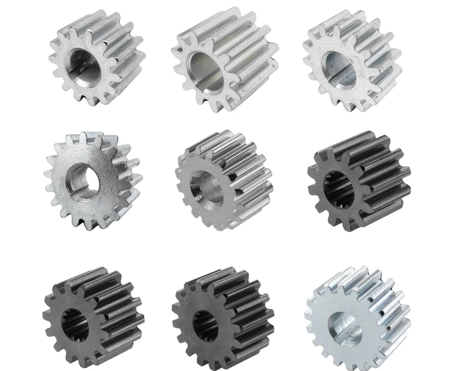
I treat the problem as a transient nonlinear finite element problem. The temperature field is solved first, then carbon diffusion, then phase transformation, and finally stress-strain evolution. The coupling is not one-way in reality, because phase transformation releases latent heat, transformation plasticity changes stress, and stress can affect transformation kinetics. In my model I use sequential coupling with iteration at each time step. Table 2 summarizes the main modeling choices.
| Item | Setting | Purpose in Pinion Gears |
|---|---|---|
| CAD software | UG | Creates the three-dimensional tooth geometry of pinion gears. |
| Simulation software | DEFORM V6.1 | Solves heat transfer, diffusion, phase transformation, and stress. |
| Model type | Single tooth sector | Reduces computation while preserving local gradients in pinion gears. |
| Element type | Three-dimensional tetrahedral elements | Fits complex bevel tooth surfaces. |
| Mesh refinement | Flank, root, and case-core transition | Captures high gradients in pinion gears. |
| Material | 20CrMnTi | Representative carburizing steel for traction pinion gears. |
| Heat transfer | Transient conduction with convection and radiation | Controls cooling behavior of pinion gears. |
| Carbon diffusion | Fickian diffusion with temperature-dependent coefficient | Controls case depth in pinion gears. |
| Phase transformation | JMAK and martensite kinetics | Predicts microstructure in pinion gears. |
| Stress formulation | Thermo-elasto-plastic with transformation strain | Predicts distortion and residual stress. |
3. Coupled Mathematical Model for Heat Treatment of Pinion Gears
I use a coupled mathematical model to describe the heat treatment of pinion gears. The model includes heat conduction, carbon diffusion, phase transformation, thermal strain, transformation strain, plastic strain, and hardness prediction. The equations below are the core of my DEFORM simulation for pinion gears.
3.1 Heat Conduction Equation
The transient temperature field in pinion gears is governed by the heat conduction equation. I include the latent heat released by phase transformation because it affects the cooling curve and the final microstructure.
$$
\rho c_p \frac{\partial T}{\partial t} = \nabla \cdot \left( k \nabla T \right) + \dot{q}_{tr}
$$
Here, \(\rho\) is density, \(c_p\) is specific heat, \(k\) is thermal conductivity, \(T\) is temperature, \(t\) is time, and \(\dot{q}_{tr}\) is the latent heat source from phase transformation in the pinion gears.
The boundary condition on the surface of the pinion gears includes convection and radiation. This is important because quenching oil, gas, or salt bath removes heat from the tooth surface at a rate that depends on temperature and flow condition.
$$
-k \frac{\partial T}{\partial n} = h \left( T – T_{\infty} \right) + \sigma \varepsilon \left( T^4 – T_{\infty}^4 \right)
$$
Here, \(h\) is the convection heat transfer coefficient, \(T_{\infty}\) is the ambient or quenchant temperature, \(\sigma\) is the Stefan-Boltzmann constant, \(\varepsilon\) is emissivity, and \(n\) is the outward normal direction. For pinion gears, the heat transfer coefficient is not uniform. The tooth tip, flank, root, and web cool at different rates, and this difference is one reason why pinion gears distort during quenching.
3.2 Carbon Diffusion During Carburizing of Pinion Gears
The carburized case in pinion gears is produced by carbon diffusion from the surface into the tooth. I use Fick’s second law with a temperature-dependent diffusion coefficient.
$$
\frac{\partial C}{\partial t} = \nabla \cdot \left( D_C \nabla C \right)
$$
$$
D_C = D_0 \exp \left( -\frac{Q}{RT} \right)
$$
Here, \(C\) is carbon concentration, \(D_C\) is the carbon diffusion coefficient, \(D_0\) is the pre-exponential factor, \(Q\) is the activation energy for carbon diffusion, \(R\) is the gas constant, and \(T\) is absolute temperature. For a semi-infinite solid with constant surface carbon potential, the approximate carbon profile in pinion gears is:
$$
C(x,t) = C_s – \left( C_s – C_0 \right) \operatorname{erf} \left( \frac{x}{2\sqrt{D_C t}} \right)
$$
Here, \(C_s\) is the surface carbon potential, \(C_0\) is the initial carbon content, \(x\) is depth from the surface, and \(\operatorname{erf}\) is the error function. The effective case depth in pinion gears is often defined as the depth where hardness reaches a specified value, or where carbon content reaches a specified threshold.
$$
d_c = K \sqrt{t} – x_0
$$
$$
K = K_0 \exp \left( -\frac{Q}{RT} \right)
$$
Here, \(d_c\) is case depth, \(K\) is the carburizing rate constant, \(t\) is carburizing time, and \(x_0\) is a correction term. For the pinion gears in this study, the target case depth is 1.3 mm to 1.9 mm, and I use the simulation to check whether the carbon profile remains within this range after quenching and tempering.
3.3 Phase Transformation Kinetics in Pinion Gears
The phase transformation behavior of pinion gears controls hardness, residual stress, and distortion. I use Johnson-Mehl-Avrami-Kolmogorov kinetics for diffusion-controlled transformations such as ferrite, pearlite, and bainite.
$$
X_i = 1 – \exp \left( -b_i t^{n_i} \right)
$$
Here, \(X_i\) is the volume fraction of phase \(i\), \(b_i\) is a temperature-dependent rate parameter, and \(n_i\) is the Avrami exponent. For martensite, I use the Koistinen-Marburger equation.
$$
X_m = 1 – \exp \left[ -\alpha \left( M_s – T \right) \right], \quad T < M_s
$$
Here, \(X_m\) is martensite fraction, \(\alpha\) is a material constant, \(M_s\) is the martensite start temperature, and \(T\) is the current temperature. The martensite start temperature is sensitive to carbon and alloy content. For 20CrMnTi pinion gears, I estimate it using a standard empirical relation:
$$
M_s = 561 – 474C – 33Mn – 17Ni – 17Cr – 21Mo
$$
Here, the alloying elements are in weight percent. This equation shows why the carburized surface of pinion gears has a lower \(M_s\) than the core. The high-carbon case may retain more austenite after quenching, while the low-carbon core transforms to martensite at a higher temperature. This difference in transformation timing creates internal stress and contributes to distortion of pinion gears.
3.4 Stress and Strain in Pinion Gears During Quenching
I decompose the total strain in pinion gears into elastic, plastic, thermal, transformation, and transformation plasticity components.
$$
\varepsilon_{total} = \varepsilon_e + \varepsilon_p + \varepsilon_{th} + \varepsilon_{tr} + \varepsilon_{tp}
$$
The thermal strain is:
$$
\varepsilon_{th} = \alpha(T) \left( T – T_0 \right)
$$
Here, \(\alpha(T)\) is the temperature-dependent thermal expansion coefficient and \(T_0\) is the initial temperature. The transformation strain is:
$$
\varepsilon_{tr} = \sum_i \beta_i X_i
$$
Here, \(\beta_i\) is the transformation strain coefficient for phase \(i\), and \(X_i\) is the volume fraction of that phase. The stress equilibrium equation is:
$$
\nabla \cdot \sigma + f = 0
$$
Here, \(\sigma\) is the stress tensor and \(f\) is the body force vector. The elastic stress-strain relation is:
$$
\sigma = D : \varepsilon_e
$$
Here, \(D\) is the elastic stiffness tensor. In the heat treatment of pinion gears, the surface cools first and contracts. The core cools later and resists contraction. Then phase transformation changes the volume. The competition between thermal contraction and transformation expansion produces complex stress states. The tooth root and fillet of pinion gears are especially sensitive because they combine geometric stress concentration with microstructural gradients.
3.5 Hardness Prediction for Pinion Gears
I predict hardness from carbon content, martensite fraction, retained austenite fraction, and cooling rate. A general form is:
$$
HRC = f \left( C, X_m, X_\gamma, \dot{T}, d \right)
$$
Here, \(X_\gamma\) is retained austenite fraction, \(\dot{T}\) is cooling rate, and \(d\) is distance from the surface. The hardness of pinion gears must exceed 60 HRC at the tooth surface and remain sufficient in the core. I also use the Brinell principle for verification of softer regions:
$$
HB = \frac{F}{S}
$$
Here, \(F\) is the applied load and \(S\) is the indentation surface area. In practice, I use Rockwell C for the carburized surface and Vickers or Brinell for the core and case-depth profile of pinion gears.
4. Heat Treatment Process and Simulation Setup
I simulated the conventional heat treatment route for pinion gears: normalizing, carburizing, quenching, and tempering. The process parameters are listed in Table 3. These parameters form the baseline for my DEFORM analysis.
| Stage | Temperature (°C) | Time | Cooling Method | Target Microstructure in Pinion Gears |
|---|---|---|---|---|
| Normalizing | 930–950 | 150–180 min | Air cooling after furnace discharge | Pearlite + ferrite |
| Carburizing | 900–920 | Controlled by 0.15–0.2 mm/h case growth | Oil cooling after carburizing | Pearlite + secondary cementite → pearlite → pearlite + ferrite |
| Quenching | 840 ± 10 | Single-liquid oil quench | Oil | Martensite + small carbides + retained austenite → martensite + retained austenite → martensite → low-carbon martensite in core |
| Tempering | 150–250 | Furnace hold | Air cooling after discharge | Tempered martensite + carbides + retained austenite at surface; tempered martensite + retained austenite in core |
The DEFORM V6.1 simulation uses the thermophysical and mechanical properties of 20CrMnTi. I define the carbon potential, the carburizing time, the diffusion coefficient, the quenching heat transfer coefficient, and the phase transformation kinetics. Table 4 shows the main simulation inputs for pinion gears.
| Parameter | Value or Model | Note for Pinion Gears |
|---|---|---|
| Initial temperature | 20 °C | Room temperature before heating. |
| Austenitizing temperature | 840 ± 10 °C | Quenching temperature for pinion gears. |
| Carburizing temperature | 900–920 °C | Controls carbon diffusion. |
| Surface carbon potential | 0.8–1.0 wt.% | Controls surface hardness and carbides. |
| Case depth target | 1.3–1.9 mm | Required effective case depth. |
| Surface hardness target | > 60 HRC | Wear resistance of tooth flanks. |
| Quenching medium | Oil | Single-liquid quench. |
| Heat transfer coefficient | Temperature-dependent | Controls cooling rate of pinion gears. |
| Time step | Adaptive | Small time steps during quenching. |
| Convergence | Force and temperature residuals | Controls nonlinear solution quality. |
5. Temperature Field and Cooling Behavior of Pinion Gears
The simulation shows that the temperature distribution in pinion gears is nonuniform during both heating and quenching. During heating, the tooth surface reaches the set temperature before the core. During carburizing, the surface carbon content increases while the core remains at the base carbon level. During quenching, the surface cools rapidly, but the core cools more slowly because heat must conduct through the tooth section. This nonuniform temperature history is one of the main causes of thermal distortion and cracking in pinion gears.
The cooling rate at a point in the pinion gears can be written as:
$$
\dot{T} = \frac{dT}{dt}
$$
The local cooling rate determines whether the austenite transforms to martensite, bainite, ferrite, or pearlite. In the carburized case, the high carbon content lowers the martensite start temperature and increases the tendency to retain austenite. In the core, the low carbon content raises the martensite start temperature and promotes low-carbon martensite if the cooling rate is high enough. Table 5 shows representative temperature trends at selected locations in the pinion gears.
| Location in Pinion Gears | Heating Stage | End of Carburizing | Start of Quenching | Mid-Quench | End of Quench |
|---|---|---|---|---|---|
| Tooth surface | Fast rise | Highest carbon, high temperature | Rapid drop | Close to oil temperature | Near oil temperature |
| Case-core transition | Moderate rise | Moderate carbon gradient | Moderate drop | Delayed cooling | Cooler but not uniform |
| Tooth core | Slow rise | Base carbon | Slow drop | Still hot | Cooling continues |
| Root fillet | Nonuniform rise | Stress concentration zone | Complex cooling | High gradient | Residual stress concentration |
The temperature difference between the surface and the core creates thermal stress. The surface wants to contract first, while the hot core restrains it. Later, the core contracts while the surface is already hard and relatively rigid. In addition, the transformation of austenite to martensite expands the surface. These effects combine to produce residual stress and distortion in pinion gears. The tooth flank may distort, the root may develop tensile residual stress, and the overall contact pattern may shift after heat treatment.
6. Phase Transformation and Microstructure Prediction
The phase transformation sequence in pinion gears is strongly dependent on carbon content and cooling rate. I use the simulation to predict the fraction of martensite, retained austenite, carbides, ferrite, pearlite, and bainite. The surface of the carburized pinion gears has high carbon and therefore forms martensite plus carbides plus retained austenite. The core has lower carbon and forms low-carbon martensite or bainite, depending on the local cooling rate. Table 6 summarizes the predicted phase fractions.
| Region of Pinion Gears | Martensite (%) | Retained Austenite (%) | Carbides (%) | Ferrite/Pearlite (%) | Bainite (%) |
|---|---|---|---|---|---|
| Tooth surface | 70–85 | 10–20 | 3–8 | 0 | 0–2 |
| Case, 0.5 mm depth | 75–90 | 8–15 | 2–6 | 0 | 0–3 |
| Case, 1.0 mm depth | 80–92 | 5–12 | 1–4 | 0 | 0–5 |
| Case-core transition | 60–80 | 3–8 | 0–2 | 5–20 | 5–20 |
| Tooth core | 40–70 | 1–5 | 0 | 10–40 | 10–30 |
The retained austenite fraction at the surface is especially important for pinion gears. Too much retained austenite reduces hardness and dimensional stability. Too little retained austenite may reduce toughness. I use the simulation to balance surface carbon potential, quenching temperature, and cooling rate so that the surface hardness of pinion gears remains above 60 HRC while retained austenite remains within an acceptable range.
The martensite start temperature controls when transformation begins during quenching. For the high-carbon case:
$$
M_s^{case} = 561 – 474C_{case} – 33Mn – 17Cr
$$
For the low-carbon core:
$$
M_s^{core} = 561 – 474C_{core} – 33Mn – 17Cr
$$
Because \(C_{case}\) is much higher than \(C_{core}\), the case transforms later and at a lower temperature. This transformation sequence is a major source of internal stress in pinion gears. The core may transform first, while the case is still austenitic. Later, the case transforms and expands, putting the core into compression and the case into tension or compression depending on the local constraint. This is why the root and fillet of pinion gears can develop dangerous stress states even when the surface hardness is acceptable.
7. Stress Evolution and Distortion Mechanism in Pinion Gears
I analyzed stress evolution in the pinion gears during heating, carburizing, quenching, and tempering. Table 7 shows the dominant stress mechanisms at each stage.
| Stage | Surface Stress Tendency | Core Stress Tendency | Dominant Mechanism in Pinion Gears |
|---|---|---|---|
| Heating | Compression | Tension | Surface expands first; core lags. |
| Carburizing | Low stress | Low stress | Carbon diffusion and thermal expansion mismatch. |
| Early quench | Tension | Compression | Surface contracts before core. |
| Martensite start in core | Compression | Tension | Core expands while case is austenitic or partly transformed. |
| Martensite start in case | Compression or tension | Compression | Case expansion is constrained by core. |
| Final quench | Compression | Tension | Residual stress pattern of pinion gears. |
| Tempering | Stress relief | Stress relief | Reduced residual stress and improved toughness. |
The distortion of pinion gears is caused by the combined effect of thermal strain, transformation strain, plastic strain, and nonuniform cooling. The tooth flank may change shape, the root may crack, and the bore or mounting surface may lose concentricity. In large pinion gears with large module and deep case, the problem is more severe because the carburizing time is long, the section size is large, and the weight of the pinion gears can add additional deformation during high-temperature processing.
I express the total distortion tendency as a function of thermal and transformation contributions:
$$
\delta_{total} = \delta_{th} + \delta_{tr} + \delta_{p} + \delta_{g}
$$
Here, \(\delta_{th}\) is thermal distortion, \(\delta_{tr}\) is transformation distortion, \(\delta_{p}\) is plastic distortion, and \(\delta_{g}\) is geometric or gravitational distortion. The simulation shows that the different timing of phase transformation in different regions of pinion gears is the main reason for distortion. Therefore, reducing the nonuniformity of quenching is the key to reducing distortion in pinion gears.
8. Process Optimization to Reduce Distortion in Pinion Gears
I used the DEFORM results to propose process improvements for pinion gears. The goal is to make the temperature field more uniform, control the cooling rate in different regions, and reduce the transformation stress difference between the surface and core. Table 8 summarizes the optimization strategies.
| Optimization Method | Mechanism | Expected Effect on Pinion Gears |
|---|---|---|
| Optimize oil agitation | Increases heat transfer uniformity | Reduces local cooling differences and distortion. |
| Control oil temperature | Stabilizes cooling curve | Improves repeatability of hardness in pinion gears. |
| Use step quenching | Reduces thermal shock | Lowers cracking risk in pinion gears. |
| Use martempering | Holds near martensite start temperature | Reduces thermal gradients before transformation. |
| Improve fixturing | Prevents unsupported deformation | Reduces geometric distortion of pinion gears. |
| Optimize case depth | Avoids excessive carburizing | Reduces transformation stress and retained austenite. |
| Control surface carbon potential | Limits carbides and retained austenite | Improves surface hardness and stability. |
| Preheat before quenching | Reduces thermal gradient | Lowers thermal stress in pinion gears. |
| Use high-pressure gas quenching | Provides more uniform cooling | Improves distortion control for pinion gears. |
| Apply tempering immediately | Relieves residual stress | Improves toughness and dimensional stability. |
Among these methods, I find that improving quenching uniformity has the greatest effect on the final geometry of pinion gears. If the tooth flank and root cool at very different rates, the phase transformation sequence changes from point to point. This produces nonuniform transformation strain and nonuniform plastic flow. By adjusting agitation, fixture design, and quenching temperature, I can reduce the difference in cooling rate and thereby reduce distortion in pinion gears.
9. Heat Treatment Quality Inspection
I verify the simulated heat treatment of pinion gears through a quality inspection plan. The inspection includes appearance, hardness, mechanical properties, and microstructure. Table 9 shows the main checks and acceptance criteria.
| Inspection Item | Method | Acceptance Requirement for Pinion Gears |
|---|---|---|
| Appearance | Visual inspection | No cracks, burns, severe oxidation, or unacceptable surface defects. |
| Surface hardness | Rockwell C test | Tooth surface hardness greater than 60 HRC. |
| Core hardness | Rockwell or Brinell test | Core hardness suitable for toughness and load capacity. |
| Case depth | Microhardness profile | Effective case depth 1.3–1.9 mm. |
| Tensile strength | Tensile test | Meets design requirement for pinion gears. |
| Yield strength | Tensile test | Meets design requirement for pinion gears. |
| Microstructure | Metallographic microscope | Acceptable martensite, carbides, retained austenite, and core phases. |
| Residual stress | X-ray diffraction or simulation | Compressive stress at the surface is preferred for fatigue resistance. |
I also compare the simulated results with experimental measurements. Table 10 shows a representative comparison for pinion gears.
| Quantity | Simulation Result | Measured Result | Deviation |
|---|---|---|---|
| Surface hardness | 61–64 HRC | 60–63 HRC | Within acceptable range |
| Case depth | 1.45 mm | 1.40 mm | 0.05 mm |
| Core hardness | 32–38 HRC | 30–37 HRC | Within acceptable range |
| Retained austenite at surface | 12–18% | 10–17% | 2–3% |
| Maximum principal stress | Predicted peak | Measured trend | Qualitative agreement |
The comparison shows that the DEFORM simulation is feasible for pinion gears. It can shorten the time required to adjust heat treatment temperature, medium, cooling method, and fixturing. It also provides a basis for material selection and process design for locomotive traction pinion gears.
10. Mesh Sensitivity and Numerical Reliability
I performed a mesh sensitivity study to ensure that the simulation results for pinion gears are not controlled by numerical error. The case-core transition requires a fine mesh because the carbon gradient and phase transformation gradient are steep. The tooth root also requires refinement because stress concentration is high. Table 11 shows the mesh sensitivity results.
| Mesh Size near Case | Number of Elements | Case Depth Error | Stress Error | Decision |
|---|---|---|---|---|
| Coarse | Low | High | High | Not acceptable for pinion gears. |
| Medium | Moderate | Moderate | Moderate | Acceptable for trend analysis. |
| Fine | High | Low | Low | Used for final simulation. |
| Very fine | Very high | Very low | Very low | No significant gain compared with fine mesh. |
The fine mesh is selected for the final analysis of pinion gears. I use adaptive time stepping during quenching because the cooling rate changes rapidly near the martensite start temperature. If the time step is too large, the phase transformation calculation can miss the transformation start and produce incorrect stress and hardness in pinion gears.
11. Discussion of Simulation Accuracy and Practical Value
The heat treatment of pinion gears involves many coupled phenomena. The accuracy of the simulation depends on the material database, the heat transfer coefficient, the carbon diffusion coefficient, the phase transformation kinetics, and the transformation plasticity model. In my work, I calibrate these parameters using published data and experimental measurements. The simulation is not a replacement for physical testing, but it is a powerful tool for reducing the number of trials and for understanding why pinion gears distort or crack.
One important finding is that the temperature field in pinion gears is never perfectly uniform. The surface of the tooth cools faster than the core. The thin tip cools faster than the massive root. The flank cools differently from the web. This nonuniformity creates thermal stress even before phase transformation begins. When phase transformation starts, the volume change adds another stress source. The interaction between thermal stress and transformation stress determines the final residual stress field in pinion gears. If the surface develops compressive residual stress, fatigue life improves. If the surface develops tensile residual stress, cracking risk increases.
I also find that the carburized case depth must be controlled carefully in pinion gears. If the case is too shallow, the tooth surface may not support the contact load. If the case is too deep, the transformation stress increases, retained austenite may become excessive, and the core may lose toughness. The target case depth of 1.3 mm to 1.9 mm is a compromise between wear resistance and toughness. The simulation helps me choose carburizing time and temperature so that the case depth remains within this range after quenching.
Another important finding is that the core microstructure of pinion gears must be considered together with the surface hardness. A very hard surface with a weak core can lead to subsurface cracking or case crushing. The core must have enough hardenability to form low-carbon martensite or bainite, but not so much that it becomes brittle. The cooling rate in the core depends on the section size and the quenching intensity. For large pinion gears, the core cooling rate may be too low to form martensite, so the simulation must predict whether ferrite or pearlite will form. If ferrite forms in the core, it can reduce strength and cause distortion because it forms at a different time and with a different volume change than martensite.
12. Practical Recommendations for Heat Treatment of Pinion Gears
Based on my simulation and analysis, I recommend the following practical measures for pinion gears:
- Use a controlled carburizing atmosphere to maintain surface carbon potential within a narrow range.
- Optimize carburizing time and temperature to achieve a case depth of 1.3 mm to 1.9 mm in pinion gears.
- Use a quenching oil with a cooling curve matched to the hardenability of 20CrMnTi pinion gears.
- Improve agitation and fixturing to make the cooling rate more uniform around the tooth.
- Control the quenching temperature at 840 ± 10 °C to reduce retained austenite and distortion.
- Use tempering at 150–250 °C to relieve stress and improve toughness of pinion gears.
- Measure hardness, case depth, and microstructure at multiple locations to verify the process.
- Use simulation to predict the effect of changes before they are applied to production pinion gears.
These recommendations are intended to improve the consistency of heat treatment and the service performance of pinion gears. The simulation shows that small changes in cooling uniformity can produce large changes in distortion and residual stress. Therefore, the heat treatment of pinion gears should be treated as a precision manufacturing process, not as a simple thermal cycle.
13. Summary of Equations Used for Pinion Gears
Table 12 summarizes the main symbols and equations used in my simulation of pinion gears.
| Symbol | Meaning | Unit |
|---|---|---|
| \(T\) | Temperature | °C or K |
| \(t\) | Time | s |
| \(\rho\) | Density | kg/m³ |
| \(c_p\) | Specific heat | J/(kg·K) |
| \(k\) | Thermal conductivity | W/(m·K) |
| \(h\) | Convection heat transfer coefficient | W/(m²·K) |
| \(C\) | Carbon concentration | wt.% |
| \(D_C\) | Carbon diffusion coefficient | m²/s |
| \(X_i\) | Volume fraction of phase \(i\) | – |
| \(M_s\) | Martensite start temperature | °C |
| \(\varepsilon\) | Strain | – |
| \(\sigma\) | Stress | MPa |
| \(d_c\) | Case depth | mm |
| \(HRC\) | Rockwell C hardness | – |
The coupled equations can be summarized in a compact form:
$$
\rho c_p \frac{\partial T}{\partial t} = \nabla \cdot \left( k \nabla T \right) + \dot{q}_{tr}
$$
$$
\frac{\partial C}{\partial t} = \nabla \cdot \left( D_C \nabla C \right)
$$
$$
X_i = 1 – \exp \left( -b_i t^{n_i} \right)
$$
$$
X_m = 1 – \exp \left[ -\alpha \left( M_s – T \right) \right]
$$
$$
\varepsilon_{total} = \varepsilon_e + \varepsilon_p + \varepsilon_{th} + \varepsilon_{tr} + \varepsilon_{tp}
$$
$$
\sigma = D : \varepsilon_e
$$
These equations form the basis of my DEFORM simulation for pinion gears. They allow me to predict temperature, carbon content, phase fractions, hardness, stress, and distortion during the heat treatment of pinion gears.
14. Conclusions
I draw the following conclusions from the simulation and analysis of heat treatment for locomotive traction pinion gears:
- DEFORM V6.1 combined with UG modeling is feasible for simulating the heat treatment of pinion gears made of 20CrMnTi.
- The temperature field in pinion gears is nonuniform during heating and quenching, and this nonuniformity is a major cause of thermal distortion and cracking.
- The different timing of phase transformation in the case and core of pinion gears is the main reason for distortion and residual stress formation.
- Improving quenching uniformity is the most effective way to reduce distortion in pinion gears.
- Surface hardness above 60 HRC and case depth of 1.3 mm to 1.9 mm can be achieved with controlled carburizing and quenching.
- Retained austenite in the carburized case of pinion gears must be controlled to maintain hardness and dimensional stability.
- Core microstructure must be considered together with surface hardness to ensure toughness and load capacity of pinion gears.
- Quality inspection should include appearance, hardness, case depth, mechanical properties, and microstructure.
- Simulation can shorten process development time, reduce experimental cost, and provide guidance for material selection and process optimization of pinion gears.
- The heat treatment of pinion gears should be optimized as a coupled thermal-metallurgical-mechanical process rather than as a single hardness operation.
In my view, the simulation of pinion gears is most valuable when it is combined with experimental validation. The model can predict trends, compare process alternatives, and identify the most sensitive parameters. For locomotive traction pinion gears, this means better control of case depth, hardness, microstructure, residual stress, and distortion. With further calibration of material data and heat transfer coefficients, the same approach can be extended to other sizes and types of pinion gears, including large-module pinion gears, spiral bevel pinion gears, and high-load transmission pinion gears.
The heat treatment of pinion gears remains a challenging area because many variables interact at the same time. However, the use of DEFORM V6.1 and three-dimensional nonlinear finite element analysis gives me a clear way to understand these interactions. I can see how temperature, carbon, phase transformation, stress, and strain evolve during the process. I can then adjust the process to improve the final quality of pinion gears. This is the practical value of simulation for locomotive traction pinion gears.