The difference between helical gear and spur gear is that the teeth of helical gear are distributed along the helix. The important feature of helical gear is its helix angle. Four groups of helical gears with different helical angles are selected for numerical simulation to analyze the influence of helical angle on the forming load, stress and strain of helical gear. The helix angle is taken separately β= 0°、 β= 12.5 ° β= 25°、 β= 37.5°。 Helix angle β= At 0 °, the gear is a spur gear, and β= 12.5 ° β= 25°、 β= At 37.5 °, the gear is helical cylindrical gear.

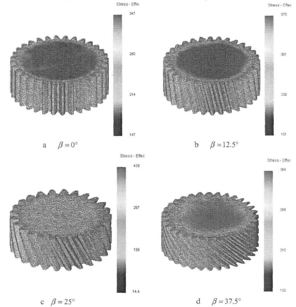
The equivalent stress distribution diagram of helical gears with different helix angles at 100% reduction is shown in Figure 2. As can be seen from the figure, the helix angle β= At 0 °, the gear is a cylindrical spur gear, and the equivalent force value at the tooth top is the largest, which is 310mpa. When helix angle β= At 12.5 °, the equivalent force value at the top of the gear tooth is also the largest, which is 315mpa. When helix angle β= At 25 °, the equivalent force value at the top of the gear tooth is 310mpa. When helix angle β= At 37.5 °, the equivalent force value at the top of the gear tooth is 315mpa. Helix angle β= 0°、 β= 12.5 ° β= 25°、 β= At 37.5 °, the distribution and magnitude of equivalent force are similar.
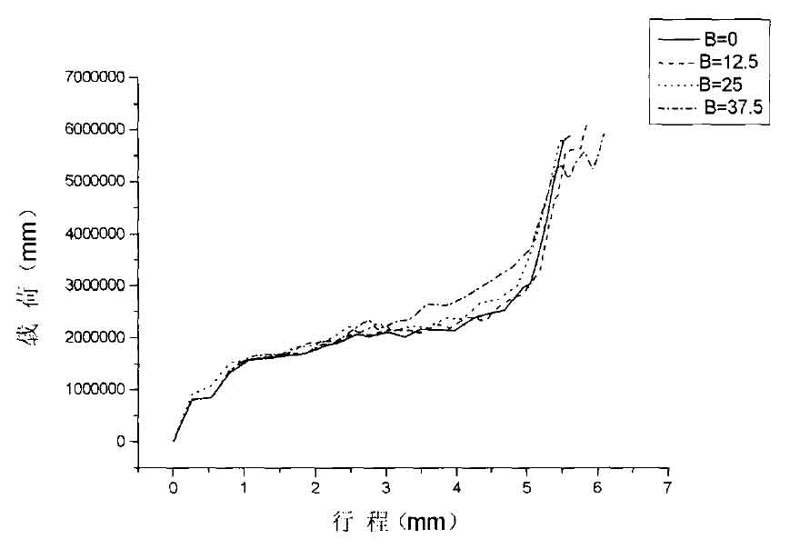
Helix angle β= 0°、 β= 12.5 ° β= 25°、 β= At 37.5 °, the stroke load curve of closed die forging of helical gear is shown in Figure 3. When helix angle β= 0 °, and its load is 5800kn. When helix angle β= At 12.5 ° · the load is 5850km. When helix angle β= At 25 °, the load is 5800kn. When helix angle β= At 37.5 °, the load is 5900kn. The load of helical gear with four groups of helix angles is the same, and its load curve is similar.