
Abstract
Helical gears offer superior load-carrying capacity, smooth transmission, and high efficiency, making them ideal for high-speed and heavy-duty applications. However, excessive contact stress and fatigue on the gear teeth are common modes of gear transmission failure. This paper presents the modeling of an external helical gear transmission system using SolidWorks and its transient contact dynamic analysis using Ansys Workbench. The deformation and stress distribution during meshing are analyzed, aiming to provide insights into gear design optimization and failure prevention.
1. Introduction
Helical gears, characterized by their inclined teeth, exhibit several advantages over spur gears, including reduced noise and vibration, improved load distribution, and smoother power transmission [1]. Nevertheless, the transient dynamics of gear meshing, especially under high loads and varying speeds, pose challenges to gear design and analysis. The high contact stresses generated during meshing can lead to tooth fatigue, wear, and ultimately gear failure.
Advancements in finite element analysis (FEA) software have facilitated the detailed study of gear contact mechanics without the need for costly and time-consuming physical testing. This paper aims to demonstrate the modeling and simulation process of an external helical gear transmission using SolidWorks and Ansys Workbench, highlighting the deformation and stress distribution during transient meshing.
2. Modeling of External Helical Gear Transmission
2.1 SolidWorks Modeling
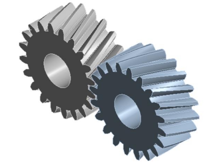
The external helical gear transmission model was created using SolidWorks, a popular computer-aided design (CAD) software. The model consisted of two helical gears, precisely assembled to ensure accurate meshing. The basic parameters of the gears are summarized in Table 1.
Table 1: Basic Parameters of Helical Gears
| Parameter | Value |
|---|---|
| Number of Teeth (z) | 20 |
| Normal Module (m) | 2 mm |
| Pressure Angle (α) | 20° |
| Helix Angle (β) | 15° |
| Addendum Coefficient (h_a*) | 1 |
| Clearance Coefficient (c*) | 0.25 |
2.2 Material Properties
Both gears were assigned the same material properties, specifically carbon steel, commonly used in gear applications due to its high strength and durability. The material properties are listed in Table 2.
Table 2: Material Properties of Carbon Steel
| Property | Value |
|---|---|
| Density | 7850 kg/m³ |
| Elastic Modulus (E) | 200 GPa |
| Poisson’s Ratio (ν) | 0.3 |
2.3 Mesh Generation
The CAD model was imported into Ansys Workbench for meshing and analysis. A tetrahedral mesh was generated for the entire model, with local mesh refinement in the contact region to accurately capture the stress gradients. the overall mesh and the locally refined mesh, respectively.
3. Finite Element Analysis
3.1 Contact Definition
The contact pair between the two helical gears was defined in Ansys Workbench, with a friction coefficient of 0.15, typical for steel-to-steel contacts. The contact surfaces are highlighted.
3.2 Boundary Conditions and Loading
Boundary conditions were applied to simulate the rotational motion of the gears. Revolute joints were defined at the centers of both gears, allowing for rotational motion. A constant torque of 1000 N·mm was applied to one gear, while a relative angular displacement of 3° was imposed on the other gear, ensuring mesh engagement.
3.3 Results and Discussion
After the simulation was completed, the deformation and stress distributions were analyzed. The deformation contour plot reveals the maximum deformation of 0.61 mm, primarily concentrated near the tooth tips and roots due to bending and contact forces.
The stress contour plot shows the maximum contact stress of 49.27 MPa, localized at the root of the engaged teeth. This high stress region is prone to fatigue crack initiation and propagation.
4. Discussion
The transient contact dynamics analysis of the helical gear transmission provides valuable insights into the stress and deformation behavior during meshing. The maximum deformation and stress values indicate the need for careful design considerations to mitigate fatigue and wear.
4.1 Stress Concentration
The high contact stress concentrated at the tooth roots is a primary concern for gear designers. This region experiences the combined effects of bending and contact stresses, making it vulnerable to fatigue failure. Design optimizations, such as tooth profile modifications or surface treatments, could help redistribute stresses and prolong gear life.
4.2 Mesh Stiffness
The mesh stiffness, defined as the resistance to deformation under load, affects the contact stress distribution. In this analysis, the uniform mesh stiffness across the tooth profile results in localized high stresses. Optimizing the mesh stiffness, for instance, by varying the tooth profile or material properties, could lead to more even stress distributions.
4.3 Lubrication
While not directly addressed in this simulation, adequate lubrication is crucial for reducing friction, wear, and contact stresses in helical gear transmissions. The use of appropriate lubricants and optimal lubrication systems can significantly improve gear performance and durability.
5. Conclusion
This paper demonstrates the modeling and transient contact dynamic analysis of an external helical gear transmission using SolidWorks and Ansys Workbench. The simulation results show that during meshing, the maximum deformation and stress are concentrated at the tooth roots, indicating the need for careful design considerations to mitigate fatigue and wear.