
The measurement of the modulus of helical gears requires first locating the center of the gear, commonly used methods include Hough transform center detection and least squares fitting detection. Due to the use of edge point to point methods, the Hough method consumes a long amount of resources. Therefore, this paper adopts a least squares fitting detection method that combines accuracy and efficiency. By minimizing the sum of squares of errors, the optimal result is obtained, which can achieve sub pixel level localization.
Error optimization function for circular equations:
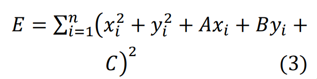
Take the minimum value of E in the equation, and according to the least squares method, after the transformation operation, the matrix must be satisfied:
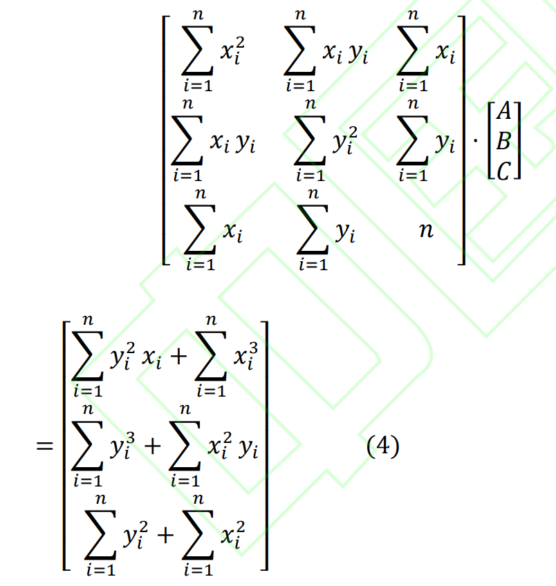
Solve the regular matrix to obtain the coordinates of the center of the circle under subpixels:
𝑥0 = −𝐴/2,𝑦0 = −𝐵/2
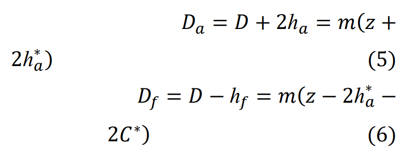
After locating the center of the helical gear, fit its minimum circumscribed circle and maximum inscribed circle through the center (x0, y0) and obtain its diameter data. According to the formula for calculating the modulus of helical gears:
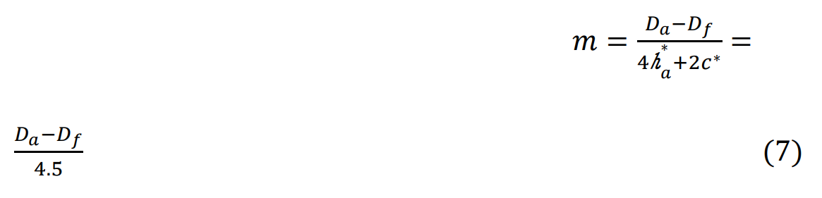
The modulus of the helical gear derived is:
After obtaining the modulus, select the closest standard modulus according to GB/T 1357-1987, as shown in the table.
| 0.1 | 0.12 | 0.15 | 0.2 | 0.25 | 0.3 | 0.4 |
| 0.5 | 0.6 | 0.8 | 1 | 0.25 | 1.5 | 2 |
| 2.5 | 3 | 4 | 5 | 6 | 8 | 10 |
| 12 | 16 | 20 | 25 | 32 | 40 | 50 |
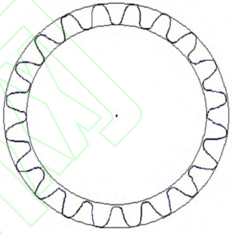
In the experiment, the tooth top circle and tooth root circle of the end face of the helical gear were fitted. After obtaining the diameter value of the tooth top circle and tooth root circle, its modulus can be calculated. The fitted edge is shown in Figure 1.
The number of teeth in a helical gear can be obtained by morphological processing of the end face image of the helical gear, and then using the detected tooth top circle and tooth root circle diameter data to calculate the diameter of the scoring circle and draw the indexing circle. The end face image can be cut using the indexing circle image to obtain each independent tooth shape area before calculating the number of teeth.
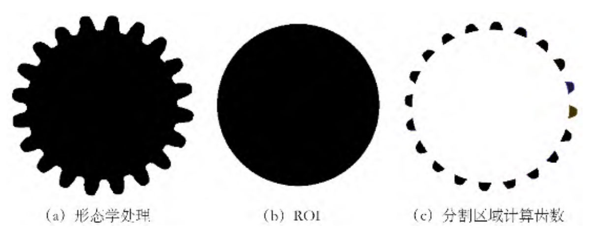
By obtaining the coordinates of the center of the circle, as well as the number of teeth and modulus, the ROI based on the helical gear indexing circle is drawn. The original area of the helical gear is cropped with the ROI to obtain the tooth shape area, and the tooth shape area is segmented into independent regions to obtain the final result. As shown in Figure 2, the final measured result is 20 teeth.