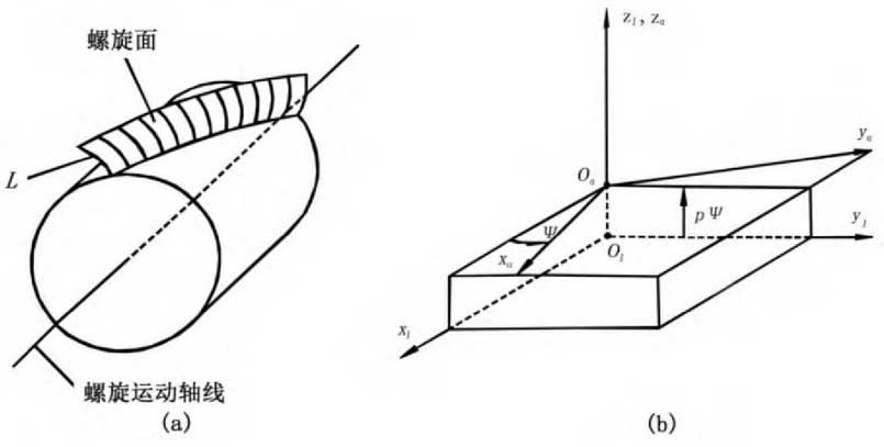
It is generally believed that there are two ways to derive the helical surface.One assumes that the helical surface is formed by the helical motion of the end profile around the gear axis, and the other is formed by the helical motion of the shaft profile.To facilitate digital modeling, the first method is used to derive the formation of helical surfaces as shown in Figure 1 (a).
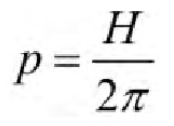
The surface equation is derived by using the principle of coordinate transformation. As shown in Figure 1 (b), the fixed coordinate system S1 and the moving coordinate system Sa with helical motion relative to S1 are established.The rotation angle and the axial displacement of the spiral motion are expressed as_and p_respectively.Here P is the helical motion parameter, the pitch of the helix, and the


Given, H is the axial displacement corresponding to a complete circle.
Assume the equation of plane curve L in coordinate system Sa

Representation that the parameter theta is an independent variable.Matrix equation for formed surface in coordinate system S1

To determine.
In

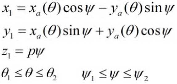
Derivable from matrix equations (3) and (4)

Equation (5) represents the helical surface with the sum of the surface coordinates.
In particular, for involute helical gears, the end face of the gear is involute and its equation in the coordinate system Sa is

Here RB is the radius of the base circle and theta is the angle at which the involute travels in the coordinate system Sa.
According to equations (5) and (6), the helical surface equation of involute helical gear can be derived as follows:

