Abstract
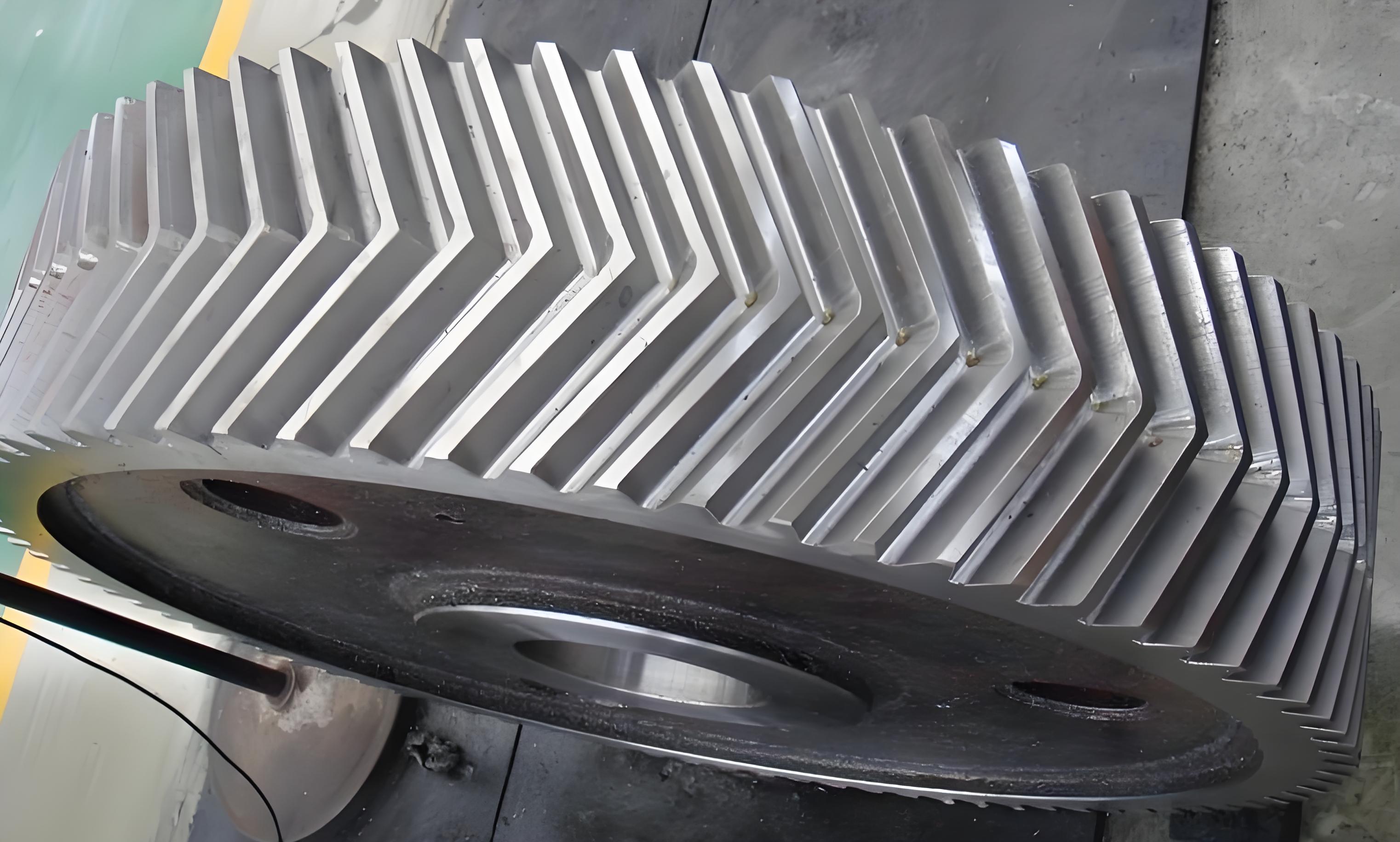
The herringbone gear, composed of two left-right symmetrical helical gears and a middle relief groove, is renowned for its strong bearing capacity and stable operation. However, due to manufacturing errors, complete symmetry of the left and right tooth surfaces cannot be guaranteed, resulting in symmetry error. This paper systematically studies the influence of symmetry error on herringbone gear meshing transmission through theoretical derivation, simulation analysis, and experimental verification.

1. Introduction
This paper delves into the research background and significance of herringbone gear meshing analysis, reviews current research on TCA, LTCA, the impact of errors and deviations on gear transmission systems, and experimental research on gear transmission systems. Building on this foundation, it defines symmetry error in herringbone gears and establishes corresponding analysis models.
Table 1: Research Status Overview
| Research Area | Key Content |
|---|---|
| TCA & LTCA | Analysis of gear tooth surface contact and load distribution |
| Error Impact | Study of how errors affect gear transmission performance |
| Experimental Research | Verification of theoretical models through experiments |
2. Theoretical Basis and Model Establishment
2.1. Gear Tooth Surface Equation Derivation
Based on gear meshing principles, the gear tooth surface equation is derived. This forms the foundation for subsequent TCA and LTCA models.
2.2. Establishment ofTCA and LTCA Models
For herringbone gears, the helical gear pair TCA model establishment method is adopted to establish the herringbone gear pair TCA model. Considering displacement coordination conditions, force balance conditions, and non-embedding contact conditions, the herringbone gear pair LTCA model is established.
Table 2: Model Components
| Model Type | Key Components |
|---|---|
| TCA Model | Gear tooth surface equation, displacement coordination, force balance |
| LTCA Model | Additional consideration of load distribution and contact conditions |
3.Herringbone Gear Pair LTCA with Symmetry Error and Verification
3.1. Definition and Modeling of Symmetry Error
Symmetry error is defined as the deviation of the actual intersection point H from the central plane O.
Table 3: Symmetry Error Definition
| Parameter | Description |
|---|---|
| ΔT | Symmetry error value |
| O | Theoretical intersection point |
| H | Actual intersection point |
3.2. Modified LTCA Model with Symmetry Error
The standard herringbone gear pair LTCA model is revised to incorporate symmetry error.
Table 4: Model Components with Symmetry Error
| Model Type | Additional Consideration |
|---|---|
| Modified TCA | Symmetry error integration |
| Modified LTCA | Updated load distribution and contact conditions |
3.3. Three-Dimensional Solid Model and Finite Element Model
Three-dimensional solid models of herringbone gears are established using parametric modeling. These models are then imported into ANSYS Workbench for finite element analysis.
Table 5: Model Preparation Steps
| Step | Description |
|---|---|
| 1 | Parametric modeling in SolidWorks |
| 2 | Model import into ANSYS |
| 3 | Material definition, mesh generation, and boundary condition setting |
3.4. Finite Element Mesh Generation and Boundary Condition Setting
The mesh is refined in the contact area to ensure accuracy. Boundary conditions simulate real-world gear constraints and loads.
Table 6: Finite Element Analysis Settings
| Setting | Value |
|---|---|
| Mesh Size (Contact Area) | 0.4mm |
| Mesh Size (Other Areas) | 1mm |
| Friction Coefficient | 0.2 |
| Torque on Drive Gear | 2000N·m |
3.5. Comparison and Verification of Gear Contact Analysis
Table 7: Comparison of Contact Patterns
| Method | Contact Pattern Description |
|---|---|
| TCA | Contact pattern with symmetry error |
| Finite Element | Similar contact pattern, slight deviation |
Table 8: Comparison of Loaded Transmission Errors
| Method | Left Mean (″) | Left Amplitude (″) | Right Mean (″) | Right Amplitude (″) |
|---|---|---|---|---|
| Finite Element | -4.9554 | 10.711 | -4.1588 | 9.332 |
| LTCA | -4.8008 | 8.659 | -3.9423 | 7.537 |
Table 9: Comparison of Meshing Stiffness
| Method | Left Mean (N/m) | Left Amplitude (N/m) | Right Mean (N/m) | Right Amplitude (N/m) |
|---|---|---|---|---|
| Finite Element | 6.5292×10^8 | 1.2598×10^8 | 5.33368562×10^8 | 1.2071351×10^8 |
| LTCA | 6.3674181×10^8 | 1.2333952×10^8 | 5.14924434×10^8 | 1.1911115×10^8 |
4. Impact of Symmetry Error and Error Compensation on Herringbone Gear Meshing Characteristics
4.1. Tooth Contact and Loaded Contact Analysis with Symmetry Error
Through case studies, the impact of symmetry error on herringbone gear meshing characteristics is analyzed.
Table 10: Impact of Symmetry Error
| Symmetry Error (ΔT) | Contact Pattern Shift | Geometric Transmission Error Range |
|---|---|---|
| 0.01mm | Slight shift | -6.123″ ~ -5.932″ |
| 0.02mm | Noticeable shift | -11.327″ ~ -10.542″ |
| 0.03mm | Significant shift | -22.614″ ~ -21.827″ |
4.2. Load Distribution with Symmetry Error
As symmetry error increases, load distribution becomes uneven, with a shift towards the tooth root on the affected side.
4.3. Error Compensation Method
A tooth surface and tooth direction compensation modification method is proposed to improve the uneven load distribution caused by symmetry error.
5. Conclusion and Future Work
Defines symmetry error in herringbone gears, establishes corresponding TCA and LTCA models, and verifies their accuracy through finite element analysis and experiments. The impact of symmetry error on herringbone gear meshing characteristics is systematically studied. Future work will focus on optimizing error compensation methods and further refining the analysis models.
