
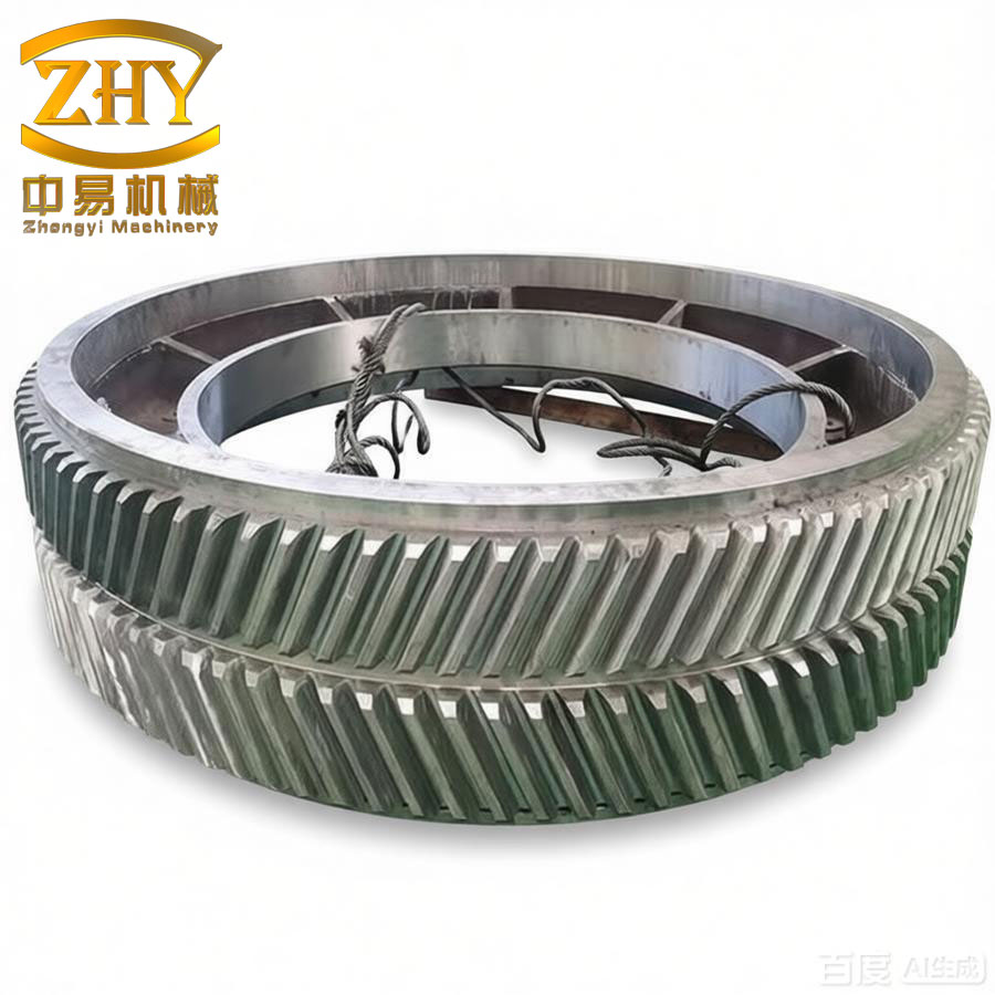
In my years of experience in heavy machinery manufacturing, I have encountered numerous challenges with herringbone gear shafts used in rolling mills. One specific design that stands out is the heavy-duty herringbone gear shaft without cutter relief groove and with medium-hard tooth surface. This type of herringbone gear shaft offers exceptional load capacity and smooth operation, making it indispensable for large equipment such as plate mills. In this article, I will share my insights into the manufacturing process of such herringbone gear shafts, focusing on key procedures and critical control points that ensure prolonged service life and compliance with stringent technical requirements. I will frequently refer to this component as herringbone gear shaft throughout the discussion.
The herringbone gear shaft without cutter relief groove is particularly challenging due to its continuous helical tooth arrangement, which demands precise heat treatment and machining to avoid distortion. Based on our production practice, I have refined a process flow that reliably produces high-quality herringbone gear shafts with uniform hardness distribution from tooth tip to root. The following sections detail each step, supported by tables and formulas derived from empirical data.
Technical Requirements
The herringbone gear shaft I will discuss is made from material equivalent to 42CrMo, with module m = 20 mm, pressure angle α = 20°, number of teeth Z = 37, helix angle β = 25°, and precision grade 8-7-7 according to ISO standards. The required hardness is 285–321 HB. These specifications impose strict demands on both raw material quality and process control. Table 1 summarizes the key technical parameters.
| Parameter | Value |
|---|---|
| Material | 42CrMo (equivalent) |
| Module m (mm) | 20 |
| Pressure angle α (°) | 20 |
| Number of teeth Z | 37 |
| Helix angle β (°) | 25 |
| Precision grade | 8-7-7 (ISO 1328) |
| Hardness range (HB) | 285–321 |
Process Flow and Critical Steps
The overall manufacturing route for the heavy-duty herringbone gear shaft is as follows: forged blank → first quenching and tempering → marking → boring and milling end faces → rough turning → rough hobbing → rough milling of flats → second quenching and tempering → semi-finish turning → finish hobbing → finish turning → finish milling of flats → inspection. I have listed the complete sequence in Table 2 with key process objectives.
| Step No. | Process | Key Purpose |
|---|---|---|
| 1 | Forging blank | Obtain required material structure |
| 2 | First quenching & tempering | Improve machinability, achieve 285–321 HB |
| 3 | Marking & milling end faces | Prepare reference surfaces |
| 4 | Rough turning | Remove excess material, leave machining allowance |
| 5 | Rough hobbing | Pre-cut tooth spaces for uniform hardening later |
| 6 | Rough milling of flats | Initial shaping of key areas |
| 7 | Second quenching & tempering | Final hardening to achieve required hardness profile |
| 8 | Semi-finish turning | Correct distortion, check runout |
| 9 | Finish hobbing | Generate final tooth profile |
| 10 | Finish turning | Final dimensions of shaft |
| 11 | Finish milling of flats | Final shape of flats |
| 12 | Inspection | Verify geometry, hardness, and precision |
Rough Turning
After the first quenching and tempering (hardness 285–321 HB), the forged blank is marked and rough turned. The allowance on the outer diameter must be determined considering the deformation that will occur during the second heat treatment. Based on my experience, an allowance of 1.8–2.0 mm on the outer diameter is appropriate for this herringbone gear shaft. The formula for the rough turned diameter \( D_{rough} \) is:
$$ D_{rough} = D_{final} + 2 \times \delta_{OD} $$
where \( D_{final} \) is the final gear outer diameter and \( \delta_{OD} \) is the allowance per side (typically 0.9–1.0 mm). Table 3 shows the recommended allowances.
| Feature | Allowance (mm) |
|---|---|
| Outer diameter (per side) | 1.8–2.0 |
| Tooth depth (per side) | 1.5–2.0 |
| Chamfer at tooth end | 1.0 × 45° |
| Root fillet radius | ≥ 3.0 |
Rough Hobbing
This is a critical step before the second quenching and tempering. The purpose is to create tooth spaces that allow uniform carburization or hardening effect from tooth tip to root during heat treatment. However, since the herringbone gear shaft in our case requires medium-hard tooth surface via quenching and tempering (not case hardening), the rough hobbing ensures that the subsequent heat treatment produces a consistent microstructure throughout the tooth profile. The tooth thickness allowance on each flank should be 0.5–1.0 mm. The root fillet radius must not be less than 3 mm to avoid stress concentration. The presence of rough-cut teeth also helps in controlling distortion by providing a more uniform cross-section compared to a solid cylinder. I have summarized the rough hobbing parameters in Table 4.
| Parameter | Value |
|---|---|
| Tooth thickness allowance (per flank) | 0.5–1.0 mm |
| Root fillet radius | ≥ 3 mm |
| Tooth end chamfer | 1.0 × 45° |
| Hob type | Single-start, roughing |
| Cutting speed | 25–35 m/min |
| Feed rate | 0.5–1.0 mm/rev |
Second Quenching and Tempering (Final Heat Treatment)
The thermal cycle for the second heat treatment is crucial for achieving the desired hardness of 285–321 HB and for minimizing distortion of the herringbone gear shaft. The herringbone gear shaft is vertically suspended in a pit furnace to ensure uniform heating and cooling. The process consists of an austenitizing stage followed by oil quenching and then tempering. Figure 1 in the original document (not reproduced here) illustrates the temperature profile; I have encoded the cycle parameters in Table 5 and a mathematical representation below.
| Stage | Temperature (°C) | Heating rate (°C/h) | Holding time (h) | Cooling method |
|---|---|---|---|---|
| Preheat 1 | 650 | 50 | 1 | — |
| Preheat 2 | 850 | 50 | 1.5–2 | — |
| Austenitizing | 850–860 | — | 1.5–2 | Oil quench: 10 min oil + 2 min air + 15 min oil (total ~27 min) |
| Tempering | 560–580 | 30 | 2.5 | Air cool to room temperature |
The heating rate during the first ramp is given by:
$$ R_1 = \frac{650 – 20}{\tau_1} $$
where \( \tau_1 \) is the time to reach 650°C from ambient (typically 12.6 hours at 50°C/h). The total cycle time for hardening is approximately 20 hours.
During quenching, the cooling curve can be described by Newton’s cooling law, but for practical control, the oil temperature is maintained at 60–80°C. The hardness after tempering can be estimated by the Hollomon-Jaffe parameter:
$$ H = f(T_{temp}, t_{temp}) $$
where a typical tempering parameter \( P = T_{temp}(\log t_{temp} + 20) \) with \( T_{temp} \) in Kelvin and \( t_{temp} \) in hours. For our herringbone gear shaft, achieving 285–321 HB corresponds to \( P \approx 20.3 \times 10^3 \).
Semi-Finish Turning
After the second heat treatment, the herringbone gear shaft inevitably experiences some distortion. The semi-finish turning step is designed to correct this. First, I measure the radial runout and bending at several axial positions. If the runout exceeds 0.3 mm, the center holes must be re-machined based on the direction and magnitude of deformation. The process is iterative: I measure, then re-center, then machine the outer diameter and faces, leaving 0.3–0.5 mm for final finish. A practical formula for the correction amount is:
$$ \Delta_{correction} = \frac{D_{max} – D_{min}}{2} $$
where \( D_{max} \) and \( D_{min} \) are the maximum and minimum diameters measured after heat treatment. This correction ensures that the remaining stock is uniformly distributed for final hobbing. Table 6 lists typical deformation values observed in our herringbone gear shafts.
| Type of Distortion | Typical Range (mm) |
|---|---|
| Radial runout at journals | 0.1–0.4 |
| Bending (total indicator reading) | 0.2–0.6 |
| Tooth lead deviation | 0.05–0.15 |
Key Concerns and Process Improvements
Determination of Stock Allowances
For the herringbone gear shaft, it is essential to leave allowance on both the outside diameter and the tooth depth before rough hobbing. If only the outer diameter is oversized, the tooth tip will experience a different hardening effect than the root. Conversely, if only the tooth depth is oversized, bending deformation becomes difficult to correct. My recommended approach is to use a balanced allowance as shown in Table 3. The total stock removed during finish hobbing is typically 0.5–1.0 mm per flank. The relationship between the rough hobbed tooth thickness \( s_{rough} \) and the final tooth thickness \( s_{final} \) is:
$$ s_{rough} = s_{final} + 2 \times \delta_s $$
where \( \delta_s \) is the per-flank allowance (0.5–1.0 mm).
Control of Deformation
The distortion of the herringbone gear shaft during the second heat treatment is influenced by many factors: material composition, prior microstructure, heating and cooling rates, and part geometry. To minimize distortion, the herringbone gear shaft should be suspended vertically in a pit furnace using a crane hook through the bore or a special fixture. The quench oil agitation must be uniform around the shaft. I have compiled a list of preventive measures in Table 7.
| Factor | Recommended Practice |
|---|---|
| Furnace loading | Vertical suspension, single part per furnace |
| Heating rate | ≤ 50°C/h below 600°C, ≤ 60°C/h above |
| Quenching | Oil at 60–80°C with controlled agitation; alternate oil-air-oil cycle |
| Pre-machining | Rough hobbing to create tooth spaces reduces section variation |
| Stress relief | Perform a stress relief anneal before final hobbing if distortion is severe |
Improved Technology for Higher Hardness
In recent developments, some manufacturers have moved to a gas carburizing process after rough hobbing and before finish hobbing to achieve a case depth of 5–6 mm for heavy-duty herringbone gear shafts. This alternative can significantly improve surface contact fatigue strength. The carburizing temperature is typically 920–950°C, followed by a diffusion period and then quenching and low-temperature tempering. The case depth profile follows Fick’s second law:
$$ \frac{\partial C}{\partial t} = D \frac{\partial^2 C}{\partial x^2} $$
where \( C \) is carbon concentration, \( D \) is diffusion coefficient, and \( x \) is depth. The effective case depth \( d_{eff} \) is determined by the time and temperature. For a herringbone gear shaft with module 20 mm, a case depth of 5 mm is recommended to balance strength and toughness. However, this process is more expensive and requires careful control of distortion because the carburizing cycle adds additional thermal cycles. Nevertheless, for the heaviest loads, it is a promising technology that I have been exploring.
Conclusion
Manufacturing a high-quality heavy-duty herringbone gear shaft without cutter relief groove demands a well-planned sequence of operations, particular attention to heat treatment distortion, and appropriate stock allowances. Through the process described—rough hobby, second quenching and tempering, semi-finish turning, and finish hobbing—the herringbone gear shaft achieves uniform hardness from tooth tip to root, thereby maximizing its service life. The use of tables and formulas in this article provides a clear reference for engineers working with this type of herringbone gear shaft. Future improvements, such as gas carburizing, may further enhance the performance of the herringbone gear shaft, especially in extreme load conditions. I hope these insights contribute to the advancement of herringbone gear shaft technology.