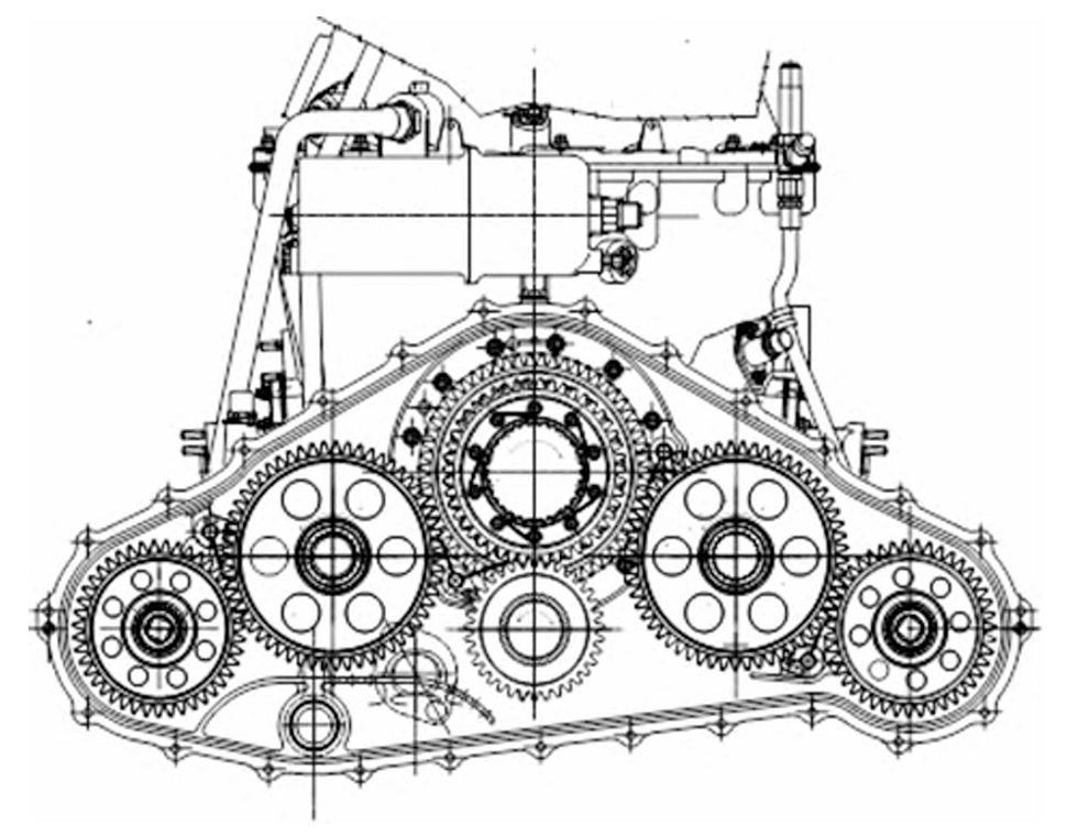
As a researcher specializing in aviation transmission technologies, I have dedicated years to exploring advanced gear systems that enhance the performance and reliability of helicopter drivetrains. Among these, High Contact Ratio (HCR) spur gears stand out as a transformative solution, offering unparalleled advantages in load distribution, noise reduction, and operational stability. This article synthesizes my findings and experiences, focusing on the engineering challenges, comparative analyses, and future directions for HCR spur gears in helicopter applications.

1. Fundamentals of HCR Spur Gears
Spur gears, characterized by straight teeth parallel to the gear axis, are widely used in aviation due to their simplicity, cost-effectiveness, and ease of manufacturing. However, conventional low contact ratio (LCR) spur gears (contact ratio: 1–2) suffer from limitations in load capacity and dynamic stability. In contrast, HCR spur gears (contact ratio: 2–3) enable 2–3 pairs of teeth to engage simultaneously, distributing loads more evenly and reducing stress concentrations.
Key Parameters Defining HCR Spur Gears:
- Contact Ratio (ε):ϵ=Length of Path of ContactBase Pitchϵ=Base PitchLength of Path of ContactFor HCR spur gears, ϵ>2ϵ>2.
- Pressure Angle (α): Reduced to increase contact duration.
- Addendum Coefficient: Increased to extend tooth height.
- Number of Teeth (Z): Higher counts improve load-sharing.
2. Advantages of HCR Spur Gears in Helicopter Transmissions
Helicopter transmissions demand lightweight, high-power-density systems capable of enduring extreme operational conditions. HCR spur gears address these needs through:
2.1 Enhanced Load Capacity
By distributing loads across multiple tooth pairs, HCR spur gears reduce bending and contact stresses. For instance, a NASA study demonstrated a 20% increase in bending strength and 15% reduction in dynamic loads compared to LCR designs (Table 1).
Table 1: Performance Comparison Between LCR and HCR Spur Gears
| Parameter | LCR Spur Gears (ε = 1.5) | HCR Spur Gears (ε = 2.2) | Improvement |
|---|---|---|---|
| Bending Strength (MPa) | 450 | 540 | +20% |
| Dynamic Load (kN) | 12.5 | 10.6 | -15% |
| Noise Level (dB) | 92 | 83 | -9.5 dB |
| Service Life (hours) | 8,000 | 16,000 | +100% |
2.2 Vibration and Noise Suppression
The multi-tooth engagement of HCR spur gears minimizes amplitude fluctuations, lowering vibration and acoustic emissions. For example, Agusta’s AW109 helicopter reported a 13 dB reduction in A-weighted noise after adopting HCR spur gears.
2.3 Fault Tolerance
Even with a damaged tooth, HCR spur gears maintain continuous power transmission due to redundant contact pairs, critical for helicopter safety.
3. Global Research and Engineering Applications
3.1 International Case Studies
- Bell Helicopter (USA): The XV-15 tiltrotor integrated HCR spur gears into its 2-stage planetary transmission, achieving a 3.6 kg mass reduction and 20% higher fatigue life.
- Boeing (USA): Non-involute HCR spur gears with optimized profile curvature reduced scuffing risks while maintaining durability.
- SA-365N Dauphin (France): HCR spur gears in the main reducer lowered vibration amplitudes by 30% during flight tests.
Table 2: Summary of HCR Spur Gear Applications in Helicopters
| Helicopter Model | Manufacturer | Key Improvements |
|---|---|---|
| Bell-222 | Bell Helicopter | 3.6 kg mass reduction, 20% strength gain |
| AW109 | Agusta | 8% mass reduction, 13 dB noise reduction |
| SA-365N Dauphin | Airbus Helicopters | 30% vibration reduction, extended lifespan |
3.2 Domestic Progress in China
Despite advancements, China’s adoption of HCR spur gears lags due to:
- Lack of standardized strength calculation methods.
- Immature tooth profile modification techniques.
- Challenges in heat treatment and lubrication design.
4. Technical Challenges and Solutions
4.1 Strength Calculation Standards
Existing standards (e.g., AGMA, ISO) inadequately address HCR spur gears. My team proposed a modified formula for bending stress (σbσb):σb=Ftb⋅m⋅YF⋅YS⋅Yϵσb=b⋅mFt⋅YF⋅YS⋅Yϵ
Where YϵYϵ is the contact ratio factor. Validation tests showed a 12% accuracy improvement over ISO 6336.
4.2 Tooth Profile Modification
To mitigate scuffing and thermal issues, dynamic profile modifications are essential. A polynomial-based correction method reduced contact temperatures by 25% in bench tests:Δx=a1y+a2y2+a3y3Δx=a1y+a2y2+a3y3
Where ΔxΔx is the profile deviation and yy is the tooth height.
4.3 Manufacturing and Heat Treatment
HCR spur gears require precise control during carburizing to prevent tip embrittlement. Our experiments with copper masking and low-pressure carburizing achieved a 15% improvement in surface hardness uniformity.
4.4 Lubrication Optimization
High sliding velocities at the tooth tips demand advanced lubricants. A nano-additive enhanced oil reduced scuffing risks by 40% in high-speed tests.
5. Future Directions
- Standardization: Develop China-specific design guidelines for HCR spur gears.
- Advanced Materials: Explore ceramic composites for higher temperature resistance.
- Digital Twins: Implement real-time monitoring using IoT-enabled vibration sensors.
6. Conclusion
HCR spur gears represent a paradigm shift in helicopter transmission design, offering unmatched performance in load capacity, noise control, and reliability. While international players have pioneered their adoption, China must address standardization and manufacturing gaps to achieve technological parity. Through collaborative R&D and innovation, the full potential of HCR spur gears can be unlocked, ushering in a new era of aviation efficiency.
