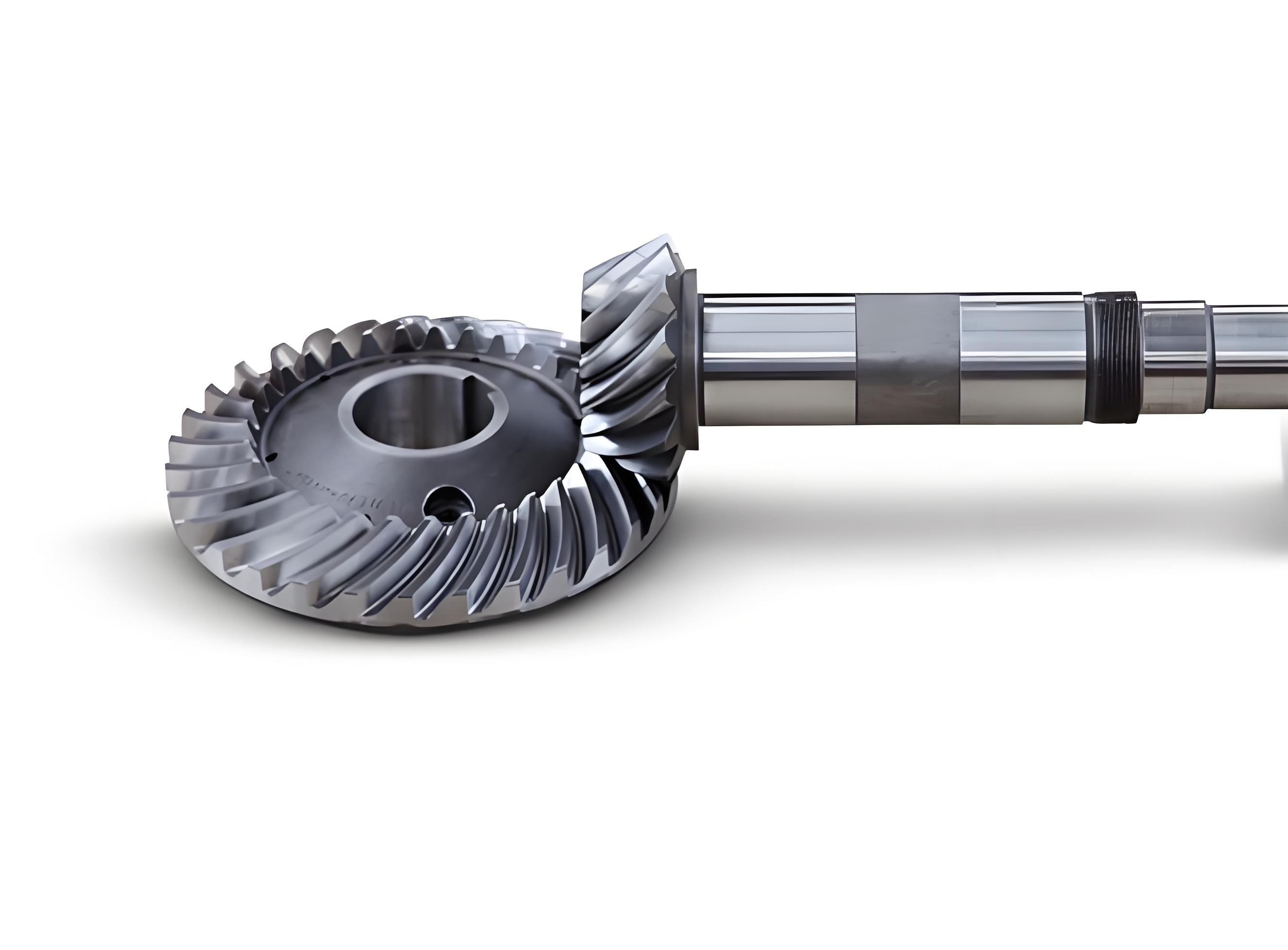
This study proposes a discrete high-order contact analysis method for spiral bevel gears by integrating ease-off topology with differential geometry. The methodology addresses limitations in traditional second-order contact analysis and establishes a computationally efficient framework using finite difference techniques.

1. Theoretical Framework
The mathematical foundation combines ease-off surface equations with gear meshing kinematics. For conjugate tooth surfaces Σ1 (pinion) and Σ2 (gear), the ease-off deviation Δδ is defined as:
$$Δδ(X,Y) = \mathbf{n}_1 \cdot (\mathbf{r}_1^c – \mathbf{r}_1)$$
where X and Y represent tooth length and height directions, respectively. The discrete ease-off surface matrix is constructed as:
$$R_e = \begin{bmatrix}
R_{11}^e & \cdots & R_{1n}^e \\
\vdots & \ddots & \vdots \\
R_{m1}^e & \cdots & R_{mn}^e
\end{bmatrix},\quad R_{ij}^e = [X_{ij}, Y_{ij}, F(X_{ij},Y_{ij})]$$
2. Higher-Order Contact Parameters
Two critical higher-order parameters are analyzed:
2.1 Transmission Ratio Derivatives
The second-order derivative of transmission ratio is derived from transmission error (TE):
$$\frac{d^2}{d\phi_1^2}\left(\frac{\phi_2}{\phi_1}\right) = \frac{z_1}{z_2} \frac{d^2Δ\phi_2}{d\phi_1^2}$$
where TE is expressed as:
$$Δ\phi_2 = \frac{z_1}{z_2}F(X,Y)$$
2.2 Geodesic Curvature of Contact Path
The contact path curvature in projection plane is calculated through:
$$\kappa_g = \frac{\frac{dX}{d\phi_1}\frac{d^2Y}{d\phi_1^2} – \frac{dY}{d\phi_1}\frac{d^2X}{d\phi_1^2}}{\left[\left(\frac{dX}{d\phi_1}\right)^2 + \left(\frac{dY}{d\phi_1}\right)^2\right]^{3/2}}$$
3. Numerical Implementation
Finite difference method discretizes the derivatives:
| Derivative | Finite Difference Scheme |
|---|---|
| First-order | $$\frac{df}{d\phi} \approx \frac{f_{i+1} – f_{i-1}}{2h}$$ |
| Second-order | $$\frac{d^2f}{d\phi^2} \approx \frac{f_{i+1} – 2f_i + f_{i-1}}{h^2}$$ |
4. Case Study: Helicopter Transmission Gears
Key parameters for the spiral bevel gear pair:
| Parameter | Pinion | Gear |
|---|---|---|
| Teeth Number | 34 | 43 |
| Module (mm) | 2.0 | |
| Pressure Angle | 20° | |
| Spiral Angle | 20° | |
4.1 Initial Tooth Surface Analysis
The baseline ease-off surface shows maximum modification of 11.21 μm. Higher-order parameters exhibit:
$$max\left|\frac{d^2K}{d\phi_1^2}\right| = 0.0009$$
$$Δ\kappa_g = 0.0002$$
4.2 Modified Surface Comparison
Three modification schemes demonstrate improved characteristics:
| Case | Δδmax (μm) | max|d²K/dφ₁²| | κg Fluctuation |
|---|---|---|---|
| Initial | 11.21 | 0.0009 | 0.0002 |
| Case 1 | 12.11 | 0.0031 | 0.0000769 |
| Case 2 | 10.23 | 0.0019 | 0.000586 |
| Case 3 | 13.18 | 0.0010 | 0.000127 |
5. Conclusion
The proposed method successfully analyzes higher-order contact characteristics of spiral bevel gears through:
- Ease-off surface discretization with 0.0000769–0.000586 geodesic curvature resolution
- Finite difference implementation requiring only O(n) computations
- Quantitative evaluation of transmission ratio derivatives (0.001–0.0031 range)
This approach enables comprehensive evaluation of spiral bevel gear contact behavior beyond traditional second-order analysis, particularly valuable for aerospace applications requiring ultra-precise motion transmission.
