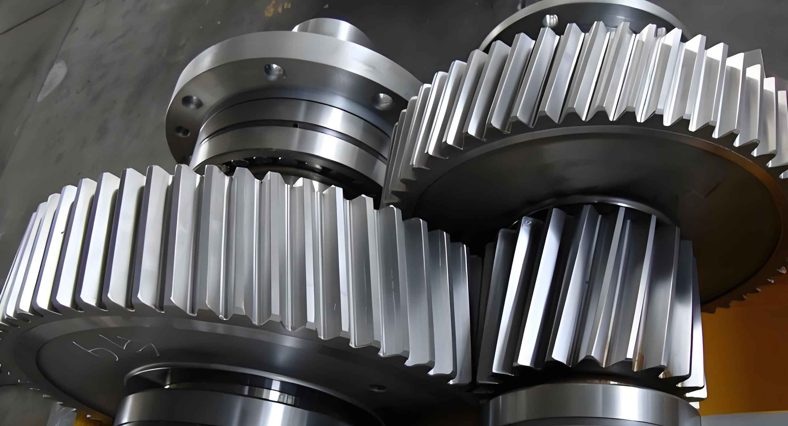
This paper presents an innovative approach for designing high-order non-circular helical gears by combining conversion method of tooth profile with intersection curves from involute helicoid surfaces. The methodology addresses inherent challenges in traditional spiral line projection while maintaining computational efficiency for practical engineering applications.
1. Fundamental Theory of Non-Circular Gearing
1.1 Pitch Curve Parameterization
The pitch curve equation for primary and driven gears in polar coordinates:
$$ \rho_1(\theta_1) = \frac{p_1}{1 – k_1\cos n_1\theta_1} $$
$$ \rho_2(\theta_2) = \frac{p_2}{1 + k_2\cos n_2\theta_2} $$
Where parameters satisfy:
$$ p_2 = \frac{n_2p_1}{n_2 – k_1^2(n_2 – 1)} $$
$$ k_2 = \frac{k_1}{n_2 – k_1^2(n_2 – 1)} $$
| Parameter | Symbol | Primary Gear | Driven Gear |
|---|---|---|---|
| Order | n | 1 | 3 |
| Eccentricity | k | 0.15 | 0.0505 |
| Module (mm) | mt | 2.8978 | 2.8978 |
1.2 Helical Line Optimization
The involute helicoid equation in parametric form:
$$ \begin{cases}
x_j = r_{bj}\cos\phi_j + u_j\cos\beta_b\sin\phi_j \\
y_j = r_{bj}\sin\phi_j – u_j\cos\beta_b\cos\phi_j \\
z_j = p_j\phi_j – u_j\sin\beta_b
\end{cases} $$
Where $p_j = r_{bj}\tan\beta_b$, demonstrating how intersection curves replace traditional spiral lines for improved meshing alignment.

2. Modeling Process for High-Order Non-Circular Helical Gears
2.1 Parameter Configuration
Key parameters for helical gear design:
$$ \beta_b = \arctan(\tan\beta\cdot\cos\alpha_t) $$
$$ m_t = \frac{m_n}{\cos\beta} $$
| Normal Module | 3mm |
| Helix Angle | 15$^{\circ}$ |
| Face Width | 50mm |
| Pressure Angle | 20$^{\circ}$ |
2.2 Curvature Analysis
Curvature radius calculation:
$$ r_{min} = \min\left[\frac{(\rho^2 + (\frac{d\rho}{d\theta})^2)^{3/2}}{\rho^2 + 2(\frac{d\rho}{d\theta})^2 – \rho\frac{d^2\rho}{d\theta^2}}\right] $$
Ensuring proper tooth root clearance:
$$ h_a^*m \leq r_{min}\sin^2\alpha $$
3. Kinematic Simulation and Verification
Motion transmission relationship:
$$ \omega_2 = \frac{\omega_1}{3.0612 – 0.6093\cos(60t)} $$
Collision detection shows maximum center distance adjustment:
$$ \Delta a = 130.658\text{mm} – 130.197\text{mm} = 0.35\% $$
4.1 Key Advantages
- Improved load distribution through optimized intersection curves
- Enhanced manufacturing efficiency via batch parameter processing
- 0.35% center distance adjustment resolving interference issues
4.2 Implementation Considerations
Critical factors for successful helical gear implementation:
$$ \beta_b = 14.08^{\circ} $$
$$ z_2 = n_2z_1 = 63 $$
Demonstrating the methodology’s effectiveness in high-order non-circular helical gear design for variable transmission applications.
