
The transmission system is the core of an automobile’s powertrain, and the spur gears within the gearbox are critical components responsible for transmitting power and torque. The precision of gear transmission ratios directly determines the overall transmission accuracy and efficiency. To achieve gearboxes with high transmission precision and low noise levels, it is imperative to enhance the contour accuracy and mechanical properties of the transmission spur gears.
Traditional gear manufacturing often relies on hot forging processes. The elevated temperatures significantly reduce the flow stress of the material, thereby improving formability and ensuring high fill rates, particularly in complex features like gear teeth. However, this method introduces several drawbacks. The formation and subsequent spalling of oxide scale on the surface during heating and cooling degrade the final surface quality. Furthermore, non-uniform cooling rates can induce residual stresses within the forged component, which are detrimental to both the dimensional stability and the integrity of the internal microstructure. These factors ultimately compromise the performance and longevity of the spur gears.
To overcome these limitations, cold precision forging has emerged as a superior alternative for producing high-quality spur gears. This process, conducted at or near room temperature, eliminates oxidation, yields excellent surface finish, and imparts high strength through work hardening. The dimensional accuracy achievable is far superior to hot forging, often requiring minimal subsequent machining. However, the cold forging of spur gears presents its own significant challenge: the high flow stress of the material at low temperatures necessitates enormous forming loads, especially to completely fill the fine, convergent geometry of the tooth tips. This high load not only demands more powerful equipment but also increases the risk of premature die failure due to excessive stress.
Therefore, the central research question becomes: How can we ensure complete die cavity filling, especially at the tooth tips, while simultaneously minimizing the required forging load during the cold precision forging of spur gears? This study employs advanced finite element method (FEM) simulation to delve into this problem, analyzing the forming characteristics of a transmission spur gear and proposing an effective die structure modification to optimize the process.
Geometric and Process Parameters for Spur Gear Cold Forging
The subject of this analysis is a representative automotive transmission spur gear. Its key geometric parameters are defined as follows:
- Number of Teeth (z): 20
- Module (m): 3 mm
- Thickness (b): 25 mm
- Tooth Profile: Involute or similar precise curvilinear profile.
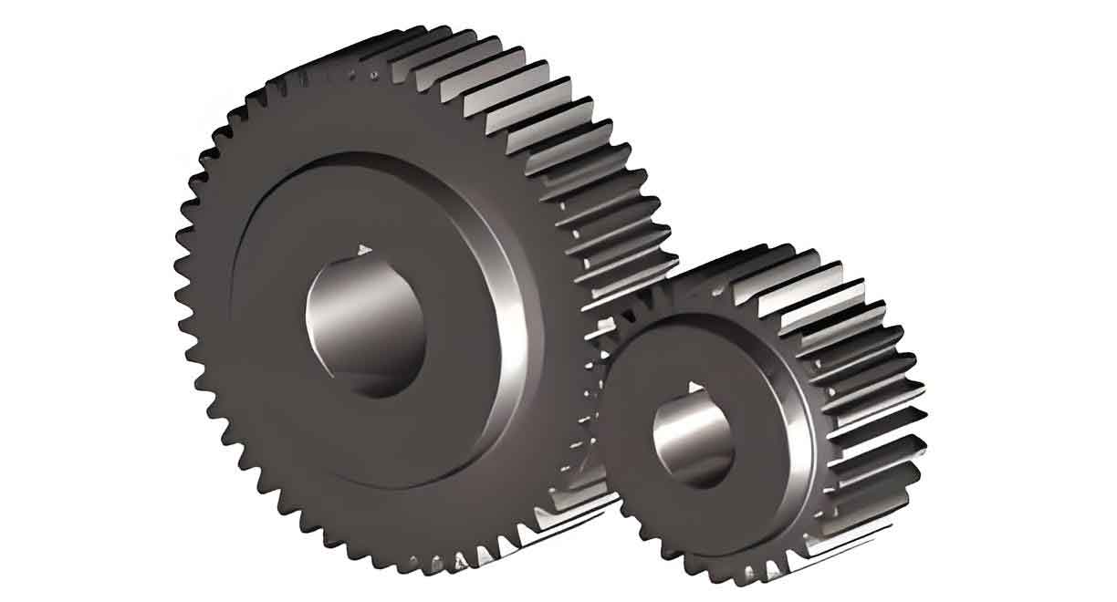
The defining feature of spur gears is their straight teeth parallel to the axis of rotation. The challenge in forging lies in the tooth tip region. As material flows radially outward from the central hub to form the teeth, it must converge into a progressively smaller volume at the tip. This natural flow pattern creates a “last-to-fill” zone at the very apex of each tooth. Ensuring complete filling here typically requires applying extremely high pressure, leading to the peak load on the forging die system.
The initial die setup for closed-die forging is conceptually straightforward, as illustrated in the schematic. It consists of a stationary lower punch, a stationary outer die (or container), and a moving upper punch. The billet is placed in the cavity. The upper punch descends at a constant velocity, compelling the material to flow radially into the tooth cavities of the stationary die. For this simulation, the punch speed was set at 1.8 mm/s. The dies (upper punch, lower punch, and outer die) are modeled as rigid bodies, while the billet is modeled as a deformable plastic body.
Material Characterization: 20CrMnMo Alloy Steel
The gear material selected is 20CrMnMo, a low-alloy carburizing steel widely used for high-strength transmission components like spur gears. Its popularity stems from an excellent combination of high core strength, good toughness, and superior hardenability. After the forging process, the spur gears are typically subjected to carburizing and heat treatment, which creates a hard, wear-resistant surface while maintaining a tough, ductile core—ideal for withstanding the contact and bending fatigue loads experienced in service.
The chemical composition and fundamental mechanical properties of 20CrMnMo are summarized in the table below. For an accurate simulation of cold forging, the plastic deformation behavior must be defined. A common approach is to use a power-law hardening model to represent the flow stress ($\sigma_f$) as a function of effective plastic strain ($\bar{\varepsilon}$) and strain rate ($\dot{\bar{\varepsilon}}$), often at a reference temperature.
For cold forging conditions (isothermal approximation), the strain rate sensitivity can sometimes be neglected for simpler steels, and the flow stress can be approximated by:
$$\sigma_f = K \bar{\varepsilon}^n$$
where $K$ is the strength coefficient and $n$ is the strain-hardening exponent. However, for more accuracy under high strain and strain rates, a model incorporating strain rate is used. A typical constitutive equation used in metal forming simulation is:
$$\sigma_f = \sigma_0 \left(1 + \frac{\bar{\varepsilon}}{\varepsilon_0}\right)^n \left(\frac{\dot{\bar{\varepsilon}}}{\dot{\varepsilon}_0}\right)^m$$
Where $\sigma_0$ is the initial yield stress, $\varepsilon_0$ is a reference strain, $\dot{\varepsilon}_0$ is a reference strain rate, $n$ is the hardening exponent, and $m$ is the strain rate sensitivity exponent (typically small for steels at room temperature).
| Property | Value | Units |
|---|---|---|
| Density ($\rho$) | 7.96 | g/cm³ |
| Young’s Modulus (E) | 220 | GPa |
| Poisson’s Ratio ($\nu$) | 0.27 | – |
| Initial Yield Strength ($\sigma_{y0}$) | ~958 | MPa |
| Tensile Strength | ~1250 | MPa |
| Strength Coefficient (K) – Approx. | ~1500 | MPa |
| Hardening Exponent (n) – Approx. | ~0.15 | – |
| Element | Content (wt.%) |
|---|---|
| C | 0.21 |
| Cr | 0.55 |
| Mn | 1.13 |
| Mo | 0.18 |
| Si | 0.19 |
| S | ≤0.03 |
| P | ≤0.03 |
| Fe | Balance |
Finite Element Simulation Analysis of the Forging Process
Using the ANSYS finite element software, a fully coupled analysis (considering large deformation plasticity) was performed to simulate the cold forging of the spur gear. The simulation tracks the evolution of key field variables: stress, strain, and material velocity. The forming process can be dissected into three characteristic stages based on the punch displacement: initial (5% reduction), intermediate (45-60% reduction), and final (95% reduction).
Stress Distribution Evolution
The effective stress (von Mises stress) distribution reveals the load-bearing state of the deforming gear. The von Mises stress is calculated as:
$$\sigma_{eff} = \sqrt{\frac{3}{2} \sigma_{ij}’ \sigma_{ij}’}$$
where $\sigma_{ij}’$ are the components of the deviatoric stress tensor.
In the initial stage, deformation is mild. The highest stresses (≈850 MPa) are concentrated on the outer cylindrical surface of the billet, where it first contacts the die wall and friction acts. The core region shows moderate stress (≈650 MPa), while the top and bottom faces in contact with the punches have the lowest stress (≈500 MPa).
During the intermediate stage, as the punch moves further, material begins to flow intensely into the tooth spaces. The stress pattern shifts dramatically. The highest stress zone (≈900 MPa) migrates to the root fillet regions of the partially formed teeth. This is a critical area where stress concentration occurs due to the abrupt change in geometry and the bending of material into the tooth cavity. The stress in other sections increases uniformly but remains below this peak.
At the final stage (95% reduction), the gear form is nearly complete. The stress field reaches its maximum intensity. The tooth tips, being the last regions to fill, now exhibit the peak effective stress, reaching approximately 950 MPa. The entire tooth region is under high stress (≈900 MPa), and even the central hub experiences elevated stress levels (≈850 MPa). This final stage clearly demonstrates the primary challenge: filling the convergent tooth tip geometry requires overcoming extremely high flow stress, leading to a sharp spike in the global forming load.
Strain Distribution and Material Flow
The effective plastic strain distribution indicates the extent of deformation and work hardening. The effective plastic strain is defined as:
$$\bar{\varepsilon} = \int \sqrt{\frac{2}{3} d\varepsilon_{ij}^p d\varepsilon_{ij}^p}$$
where $d\varepsilon_{ij}^p$ are the components of the plastic strain increment tensor.
Initially, strain is localized on the billet’s outer edges (max ≈0.11). By the intermediate stage, as teeth form, the strain concentrates massively in the tooth bodies, with the root areas seeing the highest values (≈1.66). In the final stage, the strain peaks at the tooth tips (≈2.45), with the entire tooth volume heavily strained (generally >1.5). The central hub undergoes relatively less deformation (strain ≈0.5), remaining as a less-worked core. This gradient in strain distribution is beneficial as it can lead to a graded microstructure after heat treatment.
Velocity Field Analysis
The material velocity vectors illustrate the flow pattern. Initially, the maximum velocity (≈1.26 mm/s) is observed at the free surface moving radially outward. During intermediate filling, the velocity in the tooth-forming regions increases (≈1.61 mm/s) as material is rapidly channeled into the cavities. Interestingly, in the final stage, the maximum velocity at the tooth tips decreases slightly (≈1.33 mm/s) compared to the intermediate stage. This slowdown signifies the increasing difficulty of flow as the material approaches the tightly constrained tip volume. The flow is becoming stagnant at the very apex, which is a classic symptom of an incomplete fill risk.
The simulation of the conventional fixed-die setup confirms the theoretical expectations. While the process successfully forms the spur gear, it does so at the cost of very high stresses in the final phase, particularly at the tooth tips. This translates directly into a high required forging load.
Process Innovation: The Floating Die Concept
The analysis of the fixed-die system reveals a fundamental limitation: the material’s only escape from the central hub is to flow radially outward into the teeth. In the final stage, when the teeth are nearly full, the central hub material is trapped and highly compressed, offering tremendous resistance to further punch movement. This resistance is the main contributor to the final load peak.
To mitigate this, a innovative die modification is proposed: converting the fixed outer die (container) into a floating die. In this new configuration, the outer die is not rigidly fixed. Instead, it is mounted on a spring or hydraulic cushion system that allows it to move axially (upward) against a controlled resistance. The lower punch remains stationary, and the upper punch is the active moving component.
The mechanics of this system are transformative. As the upper punch descends and begins to compress the billet, the initial radial expansion of the material pushes against the outer die wall. Once the radial pressure exceeds the pre-set resistance of the spring/cushion system, the entire outer die starts to move upward along with the deforming material. This upward movement provides an additional degree of freedom for material displacement. Essentially, the billet is not only being compressed radially outward but also being “carried” axially by the moving die. This combined motion promotes more homogeneous deformation and, crucially, reduces the intense triaxial compressive stress state in the central hub during the final filling stage. The material finds it easier to flow into the tooth cavities because it has an auxiliary axial escape path (the upward movement of the die), which relieves pressure.
The governing equilibrium for the floating die involves the balance between the frictional and forming radial force ($F_r$) on the die wall and the resisting force ($F_{spring}$) of the cushion:
$$ F_r = \mu \cdot p \cdot A_{contact} \approx F_{spring} = k \cdot x $$
where $\mu$ is the friction coefficient, $p$ is the interface pressure, $A_{contact}$ is the billet-die contact area, $k$ is the spring/damping constant, and $x$ is the die displacement. When $F_r > kx$, the die moves.
Comparative Results: Fixed Die vs. Floating Die
The proposed floating die system was modeled in the FEM simulation, and the results were compared directly with the conventional fixed-die system. The improvements are significant across multiple metrics, all contributing to a more efficient and less demanding forging process for the spur gears.
The table below summarizes the key comparative results at the critical 95% reduction stage:
| Performance Metric | Fixed Die System | Floating Die System | Improvement |
|---|---|---|---|
| Max. Effective Stress | ~950 MPa | ~890 MPa | Reduced by ~6.3% |
| Max. Effective Plastic Strain | ~2.446 | ~2.349 | Reduced by ~4.0% |
| Max. Material Velocity | ~1.33 mm/s | ~1.23 mm/s | More uniform flow |
The most dramatic and practically important result is the reduction in forging load. The plot of forging load versus time (or punch stroke) tells the definitive story. In the fixed-die case, the load increases monotonically, culminating in a sharp peak at the end of the stroke. The maximum load recorded is approximately 565 kN.
In contrast, the load curve for the floating-die system shows a markedly different profile. The load increases more gradually. More importantly, in the final stage of tooth tip filling, the load does not spike. Instead, it reaches a significantly lower maximum value of approximately 322 kN.
This represents a load reduction of:
$$\text{Load Reduction} = \frac{565 – 322}{565} \times 100\% \approx 43\%$$
A 43% reduction in the maximum required load is a profound improvement. It implies that the same spur gear can be forged on a smaller, less powerful, and potentially less expensive press. It also dramatically lowers the mean and peak stresses acting on the forging dies (punches and the outer die itself), which directly translates to reduced die wear, lower risk of catastrophic die failure (fatigue, fracture), and an overall increase in tool life. For mass production of automotive spur gears, this enhancement in die longevity is a critical economic factor.
Conclusion
This finite element simulation study provides a detailed investigation into the cold precision forging process of automotive transmission spur gears. The analysis of a conventional fixed-die system successfully maps the evolution of stress, strain, and velocity fields, clearly identifying the tooth tip region as the critical point of highest stress and potential filling difficulty, which correlates with the peak forging load.
The innovative proposal of a floating die system demonstrates a highly effective solution to this core challenge. By allowing the outer die to move axially against a controlled resistance, the process alleviates the extreme triaxial compression in the workpiece during the final filling stage. The simulation results confirm substantial benefits: a more favorable stress and strain distribution within the forged spur gear, and most significantly, a reduction of the maximum forging load by approximately 43%. This drastic load reduction offers major advantages for industrial application, including the use of smaller-capacity presses and greatly extended die service life.
Therefore, the implementation of a floating die structure is a validated and recommended strategy for optimizing the cold precision forging of high-quality, high-strength spur gears for automotive transmissions, enabling more economical and reliable production.