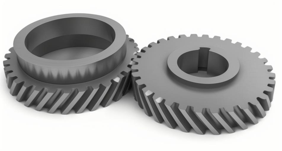
To enhance the modeling accuracy of diagonal modified helical gears and address the non-smooth transition at the tooth root, this study proposes a CATIA-based reverse modeling method using MATLAB for full tooth surface coordinate calculation and a Hermite interpolation technique for the tooth root transition zone. A coordinate system for the imaginary generating rack is established to derive equations for standard working tooth surfaces and root transition surfaces. A modified tooth surface is generated by superimposing a modification surface along the normal direction of the standard tooth surface, followed by Hermite interpolation to ensure smooth transitions. The resulting 3D model achieves a maximum fitting deviation of 1.1 μm, meeting high-precision design requirements.
Mathematical Modeling of Full Tooth Surfaces
Standard Involute Surface
The coordinate transformation for generating the right tooth surface of a helical gear using a virtual rack cutter is shown in Figure 1. The position vector $\mathbf{r}_1(u_t, l_t, \theta_1)$, unit normal vector $\mathbf{n}_1(u_t, l_t, \theta_1)$, and meshing equation are expressed as:
$$
\begin{cases}
\mathbf{r}_1(u_t, l_t, \theta_1) = \mathbf{M}_{1t} \cdot \mathbf{r}_t(u_t, l_t) \\
\mathbf{n}_1(u_t, l_t, \theta_1) = \mathbf{L}_{1t} \cdot \mathbf{n}_t(u_t, l_t) \\
f = \mathbf{n}_1 \cdot \frac{\partial \mathbf{r}_1}{\partial \theta_1} = 0
\end{cases}
$$
where $\mathbf{M}_{1t}$ represents the transformation matrix from the rack coordinate system $S_t$ to the gear coordinate system $S_1$, and $\mathbf{L}_{1t}$ is the submatrix excluding the last row and column of $\mathbf{M}_{1t}$.
Tooth Root Transition Curve
The position vector $\mathbf{r}’_t(\phi_t, l_t)$ and normal vector $\mathbf{n}’_t(\phi_t, l_t)$ of the rack’s transition arc (radius $r_w = 0.25m_n / (1 – \sin\alpha_n$) are derived as:
$$
\begin{cases}
\mathbf{r}’_1(\phi_t, l_t, \theta_1) = \mathbf{M}_{1t} \cdot \mathbf{r}’_t(\phi_t, l_t) \\
\mathbf{n}’_1(\phi_t, l_t, \theta_1) = \mathbf{L}_{1t} \cdot \mathbf{n}’_t(\phi_t, l_t) \\
f = \mathbf{n}’_1 \cdot \frac{\partial \mathbf{r}’_1}{\partial \theta_1} = 0
\end{cases}
$$
where $\phi_t \in [0, \pi/2 – \alpha_n]$.
Diagonal Modification of Helical Gear Tooth Surfaces
Diagonal modification involves profile corrections at the gear meshing entry/exit regions. The modification boundaries are defined by:
| Parameter | Tooth Tip | Tooth Root |
|---|---|---|
| Modification Curve | Quadratic | Quadratic |
| Modification Height (mm) | 5.0 | 5.0 |
| Maximum Modification (μm) | 30.0 | 30.0 |
The modified tooth surface combines standard involute surfaces with normal-direction modifications:
$$
\mathbf{r}_{1m}(u_t, l_t, \theta_1) = \mathbf{r}_1(u_t, l_t, \theta_1) + \delta(z_2, x_2)\mathbf{n}_1(u_t, l_t, \theta_1)
$$
where $\delta(z_2, x_2)$ represents the modification function. Hermite interpolation ensures continuity between modified and transition surfaces:
$$
\mathbf{r}(t) = (2t^3 – 3t^2 + 1)\mathbf{P}_0 + (-2t^3 + 3t^2)\mathbf{P}_1 + (t^3 – 2t^2 + t)\mathbf{T}_0 + (t^3 – t^2)\mathbf{T}_1
$$
Reverse Modeling and Accuracy Verification
Discrete coordinates of the modified helical gear tooth surfaces are generated via MATLAB and imported into CATIA V5 R20 for point cloud reconstruction. Key parameters for the helical gear pair are:
| Parameter | Pinion | Gear |
|---|---|---|
| Teeth | 30 | 72 |
| Module (mm) | 5.0 | |
| Helix Angle (°) | 33.273 | |
Deviation analysis in CATIA demonstrate maximum fitting errors:
| Direction | Left Flank (μm) | Right Flank (μm) |
|---|---|---|
| Profile | 1.103 | 0.691 |
| Lead | 0.636 | 0.380 |
The final 3D model confirms that diagonal modification effectively reduces stress concentration while maintaining geometric accuracy. This methodology provides a reliable foundation for CAE analysis and precision manufacturing of low-noise helical gear systems.
