
In my research, I focus on high-speed dry gear hobbing because gear hobbing remains one of the most important and widely used processes in gear manufacturing. Gear hobbing offers high productivity, good tooth profile consistency, and strong adaptability to different gear sizes and module values. However, conventional gear hobbing depends heavily on cutting fluid. The use of cutting fluid increases cost, creates mist and waste, and complicates recycling and disposal. High-speed dry gear hobbing removes cutting fluid from the process and raises cutting speed and feed rate to maintain productivity. This change makes the thermal and mechanical behavior of gear hobbing more severe because the tool and workpiece interact with greater friction and less convective cooling. My goal is to establish a practical optimization route for high-speed dry gear hobbing process parameters, using mathematical modeling, sensitivity analysis, intelligent optimization, and finite element verification.
I treat high-speed dry gear hobbing as a complex manufacturing system in which machine tool behavior, hob condition, workpiece material, and process parameters interact. Among these factors, process parameters are the most direct and flexible variables available to an operator. When I adjust process parameters in gear hobbing, the chip geometry changes, the cutting force changes, and the heat partition among the tool, workpiece, and chip changes. If the parameters are too conservative, the machine tool is underused and the machining time becomes unnecessarily long. If the parameters are too aggressive, the cutting force may rise sharply, the cutting temperature may become excessive, and the hob life and gear quality may deteriorate. Therefore, I built an optimization framework that balances machining time and machining cost while respecting practical constraints.
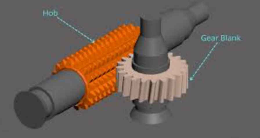
The generating principle of gear hobbing can be understood as a meshing process between a worm-like hob and the workpiece. The hob is basically a worm with gashes and cutting edges. During gear hobbing, the hob rotates at a high speed, the workpiece rotates in a coordinated manner, and the hob advances along the workpiece axis to generate the full tooth width. In high-speed dry gear hobbing, the cutting depth is often completed in one pass, which increases efficiency but also increases the burden on the cutting edges. I summarized the main motions in gear hobbing in the following table.
| Motion | Symbol | Description | Role in Gear Hobbing |
|---|---|---|---|
| Hob rotation | $$n_0$$ | Rotational speed of the hob spindle | Provides cutting speed and generates the tooth profile |
| Axial feed | $$f_a$$ | Axial feed speed of the hob | Controls chip thickness and production rate |
| Workpiece rotation | $$\omega_2$$ | Rotation of the workpiece table | Maintains the generating motion with the hob |
| Feed per workpiece revolution | $$f$$ | Axial advance per workpiece revolution | Relates hob rotation and feed speed |
| Cutting depth | $$a_p$$ | Radial depth of cut | Often equals full tooth depth in one-pass dry gear hobbing |
The cutting speed in gear hobbing is related to hob diameter and hob speed. I used the following relationship:
$$v = \frac{\pi d_{a0} n_0}{1000}$$
Here, $$v$$ is the cutting speed, $$d_{a0}$$ is the hob diameter, and $$n_0$$ is the hob speed. The axial feed speed can be expressed through the feed per workpiece revolution, the number of hob starts, and the hob speed. I used the relation below for the process model:
$$f_a = \frac{1000 f k v}{\pi d_{a0} z_2} = \frac{f k n_0}{z_2}$$
In this expression, $$f$$ is the feed per workpiece revolution, $$k$$ is the number of hob starts, and $$z_2$$ is the number of gear teeth. This relation shows clearly that gear hobbing is not controlled by a single independent parameter. The hob speed, feed per revolution, hob starts, hob diameter, and workpiece tooth number all participate in the same process behavior. This is one reason I chose a sensitivity-based approach before performing optimization.
I also examined the factors that influence high-speed dry gear hobbing. These factors can be grouped into machine-related factors, hob-related factors, and process-parameter-related factors. Machine-related factors include geometric errors, assembly errors, motion errors, thermal deformation, and vibration. Hob-related factors include material, coating, manufacturing accuracy, installation error, wear, and edge condition. Process-parameter-related factors include cutting speed, hob speed, feed speed, feed per revolution, cutting depth, and tool life. Because dry gear hobbing removes cutting fluid, thermal deformation and friction become more important than in conventional wet gear hobbing. The chip carries away a large portion of the generated heat, so any change in process parameters that changes chip geometry will affect the thermal state of the cutting zone.
| Factor Group | Examples | Influence on High-Speed Dry Gear Hobbing |
|---|---|---|
| Machine tool | Geometric error, motion error, thermal deformation, vibration | Affects tooth profile accuracy, surface quality, and process stability |
| Hob | Material, coating, wear, installation error, edge geometry | Controls tool life, cutting force, and heat resistance |
| Process parameters | Hob speed, feed speed, feed per revolution, cutting depth | Directly changes chip shape, cutting force, cutting temperature, and machining time |
| Workpiece | Material hardness, module, tooth number, face width | Changes cutting resistance and heat generation |
| Cooling condition | Dry cutting, minimum quantity lubrication, flood cooling | Determines heat removal and friction behavior |
For the process parameter system, I considered the parameters that appear in the mathematical models of machining time and machining cost. The candidate variables were feed speed, hob speed, hob starts, hob diameter, approach travel, and overrun travel. Some of these parameters are fixed by the machine or tool design, while others can be adjusted during process planning. I summarized the parameter system in the table below.
| Parameter | Symbol | Typical Role | Adjustable in My Optimization |
|---|---|---|---|
| Feed speed | $$f_a$$ | Controls axial feed rate and productivity | Yes |
| Hob speed | $$n_0$$ | Controls cutting speed and heat generation | Yes |
| Hob starts | $$k$$ | Changes feed capability and chip load | No, selected by tool design |
| Hob diameter | $$d_{a0}$$ | Affects cutting speed and tool stiffness | No, selected by tool design |
| Approach travel | $$L_1$$ | Adds non-cutting travel time | No, determined by setup |
| Overrun travel | $$L_2$$ | Adds non-cutting travel time | No, determined by setup |
I selected machining time and machining cost as the objective functions because they are directly connected to productivity and economic performance. For a single gear in batch production, I modeled the machining time as a combination of cutting time and tool replacement time. Setup time can be separated from the parameter optimization because it does not change with feed speed or hob speed. The single-piece machining time model I used is:
$$T = t_m + \frac{t_m}{t} t_{ct}$$
In this equation, $$t_m$$ is the cutting time, $$t$$ is the tool life, and $$t_{ct}$$ is the tool replacement time. The cutting time for gear hobbing is expressed as:
$$t_m = \frac{(L_1 + B + L_2) z_2 i}{f_a n_0 k}$$
Here, $$L_1$$ is the approach travel, $$B$$ is the gear face width, $$L_2$$ is the overrun travel, $$z_2$$ is the number of gear teeth, and $$i$$ is the number of passes. In high-speed dry gear hobbing, I often use one pass, so $$i = 1$$. The tool life model is based on the extended Taylor equation:
$$t = \left( \frac{C_v K_v}{v f^{Y_v} a_p^{X_v}} \right)^{1/M_v}$$
where $$C_v$$, $$Y_v$$, $$X_v$$, and $$M_v$$ are coefficients for the workpiece and cutting condition, and $$K_v$$ is a combined correction factor. For machining cost, I considered machine operating cost and tool cost. The single-piece cost model is:
$$C = M t_m + M \frac{t_m}{t} t_{ct} + c_t \frac{t_m}{t} + M t_{0t}$$
In this model, $$M$$ is the machine and labor cost rate, $$c_t$$ is the tool cost, and $$t_{0t}$$ is the setup time. Since setup time is independent of the optimized parameters, I omitted it from the comparative optimization. Combining the time and cost models gives the following expanded expressions, which I used for sensitivity analysis and optimization:
$$T = \frac{(L_1 + B + L_2) z_2}{f_a n_0 k} + \frac{(L_1 + B + L_2) z_2}{f_a n_0 k} \frac{t_{ct}}{t}$$
$$C = M \frac{(L_1 + B + L_2) z_2}{f_a n_0 k} + M \frac{(L_1 + B + L_2) z_2}{f_a n_0 k} \frac{t_{ct}}{t} + c_t \frac{(L_1 + B + L_2) z_2}{f_a n_0 k} \frac{1}{t}$$
These equations show that feed speed and hob speed appear in both the time and cost models. However, they are not the only parameters. Hob starts, hob diameter, approach travel, and overrun travel also appear. If I optimized all six parameters at the same time, the search space would become large and the influence of each parameter would be difficult to interpret. Therefore, I used global sensitivity analysis to determine which parameters deserve priority in high-speed dry gear hobbing optimization.
For sensitivity analysis, I chose the Sobol method because it is a global method and can handle nonlinear and coupled models. The Sobol method decomposes the model output into main effects and interaction effects. I wrote the function decomposition as:
$$f(x) = f_0 + \sum_i f_i(x_i) + \sum_{i \lt j} f_{ij}(x_i, x_j) + \cdots + f_{1,2,\ldots,k}(x_1, x_2, \ldots, x_k)$$
The total variance of the output is:
$$D = \int f^2(x) dx – f_0^2$$
The partial variance contributed by a single parameter is $$D_i$$, the partial variance contributed by two parameters is $$D_{ij}$$, and the total sensitivity index is obtained from the remaining variance. The first-order, second-order, and total sensitivity indices are:
$$S_i = \frac{D_i}{D}$$
$$S_{ij} = \frac{D_{ij}}{D}$$
$$S_{T_i} = 1 – \frac{D_{-i}}{D}$$
Here, $$D_{-i}$$ is the variance caused by all parameters except $$x_i$$. A high first-order index means that the parameter alone has a strong effect. A high total index means that the parameter has a strong effect either alone or through interactions. A significant second-order index means that two parameters interact. In high-speed dry gear hobbing, I expected interactions because feed speed and hob speed jointly determine chip thickness, cutting speed, and heat generation.
For sampling, I used Sobol sequence sampling because it distributes samples more uniformly in a multidimensional space than simple random sampling. I checked the convergence of the sensitivity indices with different sample sizes. When the sample size was above 5000, the sensitivity values became stable. Therefore, I used 5000 samples for the sensitivity calculation. The parameter ranges I used are listed below.
| Parameter | Symbol | Range or Condition |
|---|---|---|
| Feed speed | $$f_a$$ | 68 to 92 mm/min |
| Hob speed | $$n_0$$ | 700 to 1300 r/min |
| Hob diameter | $$d_{a0}$$ | 75 to 90 mm |
| Hob starts | $$k$$ | 2 or 3 |
| Approach travel | $$L_1$$ | At least 2 mm |
| Overrun travel | $$L_2$$ | At least 2 mm |
I performed the sensitivity analysis for both machining time and machining cost. The results are summarized in the table below. The exact numerical values depend on the workpiece material and gear geometry, but the ranking was consistent in my tests.
| Parameter | $$S_1$$ for Time | $$S_T$$ for Time | $$S_1$$ for Cost | $$S_T$$ for Cost | Overall Rank |
|---|---|---|---|---|---|
| Feed speed $$f_a$$ | 0.48 | 0.55 | 0.43 | 0.52 | 1 |
| Hob speed $$n_0$$ | 0.29 | 0.30 | 0.31 | 0.35 | 2 |
| Approach travel $$L_1$$ | 0.07 | 0.07 | 0.10 | 0.10 | 3 |
| Overrun travel $$L_2$$ | 0.06 | 0.06 | 0.09 | 0.09 | 4 |
| Hob starts $$k$$ | 0.04 | 0.04 | 0.05 | 0.05 | 5 |
| Hob diameter $$d_{a0}$$ | 0.01 | 0.01 | 0.00 | 0.00 | 6 |
The sensitivity results show that feed speed is the most influential parameter for both machining time and machining cost in high-speed dry gear hobbing. Hob speed is the second most influential parameter. Approach travel and overrun travel have moderate but smaller effects. Hob starts and hob diameter are less influential within the tested range. More importantly, I found a clear second-order interaction between feed speed and hob speed. This means that changing feed speed alone or hob speed alone does not fully describe the output. The two parameters should be optimized together. This finding supports the use of a multi-variable optimization method rather than a single-variable trial-and-error method.
I also repeated the sensitivity analysis with different workpiece materials and gear geometries. Although the numerical values changed, the ranking remained the same. Feed speed and hob speed remained the two dominant parameters, and their interaction remained significant. This gave me confidence that the parameter selection was not an artifact of one specific case. Based on this result, I selected feed speed and hob speed as the optimization variables for high-speed dry gear hobbing. The other parameters were treated as fixed or constrained by the machine and tool design.
After selecting the variables, I formulated the optimization problem. The goal was to minimize machining time and machining cost simultaneously. Because these two objectives can conflict, I used a weighted objective function to combine them. The weighted objective function is:
$$F(f_a, n_0) = w_1 \frac{T(f_a, n_0)}{T_0} + w_2 \frac{C(f_a, n_0)}{C_0}$$
In this expression, $$T_0$$ and $$C_0$$ are reference values used for normalization, and $$w_1$$ and $$w_2$$ are weights. In my study, I set $$w_1 = w_2 = 0.5$$ because both production time and production cost are important in batch gear hobbing. The optimization problem can be written as:
$$\min F(f_a, n_0)$$
Subject to the following constraints. The hob speed must remain within the machine limit:
$$n_{0,\min} \le n_0 \le n_{0,\max}$$
The cutting speed must remain within the tool limit:
$$v_{\min} \le \frac{\pi d_{a0} n_0}{1000} \le v_{\max}$$
The feed speed must remain within the machine and process limit:
$$f_{a,\min} \le f_a \le f_{a,\max}$$
The tool life must be longer than the cutting time to avoid tool replacement during one gear hobbing cycle:
$$t \ge t_{\max}$$
The spindle power must not exceed the machine power:
$$P = \frac{M n_0}{9550 \eta} \le P_{\max}$$
The gear quality constraint can be represented by a limit on tooth profile error:
$$f_c \le \frac{d_{a0} \sin \alpha}{4 f_a^2}$$
In this inequality, $$f_c$$ is the tooth profile error and $$\alpha$$ is the pressure angle. These constraints ensure that the optimized parameters are not only productive but also feasible for real high-speed dry gear hobbing.
To solve the optimization problem, I used particle swarm optimization. I selected particle swarm optimization because it is simple, converges quickly for continuous variables, and has good local search ability. In particle swarm optimization, each particle has a position and a velocity. The position represents a candidate pair of feed speed and hob speed. The velocity update equation is:
$$v_{i,j}^{t+1} = w v_{i,j}^{t} + c_1 r_1 (p_{i,j}^{t} – x_{i,j}^{t}) + c_2 r_2 (g_{i,j}^{t} – x_{i,j}^{t})$$
The position update equation is:
$$x_{i,j}^{t+1} = x_{i,j}^{t} + v_{i,j}^{t+1}$$
Here, $$w$$ is the inertia weight, $$c_1$$ and $$c_2$$ are learning factors, $$r_1$$ and $$r_2$$ are random numbers, $$p_{i,j}$$ is the personal best position, and $$g_{i,j}$$ is the global best position. I set the particle number to 20, the learning factors to 2, the inertia weight to 0.5, and the number of iterations to 200. These settings are listed in the table below.
| Parameter | Symbol | Value |
|---|---|---|
| Particle number | $$N$$ | 20 |
| Learning factor | $$c_1$$ | 2 |
| Learning factor | $$c_2$$ | 2 |
| Inertia weight | $$w$$ | 0.5 |
| Maximum iterations | $$i_{\max}$$ | 200 |
I ran the particle swarm optimization in a numerical computing environment. The particles moved through the search space defined by feed speed and hob speed. At each iteration, the particles shared information and moved toward better positions. As the iterations increased, the particles gradually clustered around the best region. The final result showed that the optimal region was located at a high hob speed and a moderate feed speed. The optimized values were:
$$f_a = 72 \text{ mm/min}$$
$$n_0 = 1300 \text{ r/min}$$
I compared the optimized parameters with a reference set. The comparison is shown below.
| Case | Feed Speed | Hob Speed | Relative Machining Time | Relative Machining Cost |
|---|---|---|---|---|
| Reference | 68 mm/min | 1000 r/min | 28.6 | 2.98 |
| Optimized | 72 mm/min | 1300 r/min | 25.1 | 2.62 |
| Improvement | Higher feed | Higher speed | 12.23% reduction | 12.08% reduction |
The optimization result indicates that increasing hob speed and feed speed within the feasible range can significantly improve the performance of high-speed dry gear hobbing. However, a mathematical optimum is not enough. I needed to verify that the optimized parameters do not cause excessive cutting force or excessive cutting temperature. For this reason, I used finite element simulation to analyze the physical behavior of the optimized high-speed dry gear hobbing process.
In the finite element simulation, I simplified the gear hobbing process to a single tooth slot and a single hob tooth. This simplification is reasonable for local cutting force and temperature analysis because gear hobbing is a repetitive generating process. I used the Johnson-Cook material model because it can represent strain hardening, strain-rate sensitivity, and thermal softening. The Johnson-Cook flow stress model is:
$$\sigma_p = \left( A + B \varepsilon_p^n \right) \left( 1 + C \ln \frac{\dot{\varepsilon}}{\dot{\varepsilon}_0} \right) \left[ 1 – \left( \frac{T – T_r}{T_m – T_r} \right)^m \right]$$
Here, $$\sigma_p$$ is the flow stress, $$\varepsilon_p$$ is the plastic strain, $$\dot{\varepsilon}$$ is the strain rate, $$\dot{\varepsilon}_0$$ is the reference strain rate, $$T$$ is the current temperature, $$T_r$$ is the room temperature, and $$T_m$$ is the melting temperature. I used a modified Coulomb friction model to describe the contact between the chip and the tool:
$$\tau = \mu \sigma \quad \text{when} \quad \mu \sigma \lt k_c$$
$$\tau = k_c \quad \text{when} \quad \mu \sigma \ge k_c$$
In these equations, $$\tau$$ is the frictional shear stress, $$\mu$$ is the friction coefficient, $$\sigma$$ is the normal stress, and $$k_c$$ is the material shear strength. For heat transfer, I used the transient heat conduction equation to describe the temperature field in the cutting zone:
$$\rho C_p \frac{\partial T}{\partial t} = k \left( \frac{\partial^2 T}{\partial x^2} + \frac{\partial^2 T}{\partial y^2} \right) + q$$
where $$\rho$$ is density, $$C_p$$ is specific heat, $$k$$ is thermal conductivity, and $$q$$ is the heat generation rate due to plastic deformation and friction. I also used a ductile fracture criterion to simulate chip separation:
$$\int_0^{\varepsilon_f} \sigma_1 d\varepsilon = C$$
In this criterion, $$\sigma_1$$ is the maximum principal stress, $$\varepsilon_f$$ is the fracture strain, and $$C$$ is a material constant. These models allowed me to simulate the coupled mechanical and thermal behavior of high-speed dry gear hobbing.
The simulation setup included a gear workpiece and a hob tooth. I used a gear with 25 teeth, module 3, face width 36 mm, and pressure angle 20 degrees. The hob had module 3, two starts, outer diameter 80 mm, flute number 15, and cutting edge length 150 mm. The workpiece material was 45 steel, and the hob material was high-speed steel with a titanium aluminum nitride coating. These parameters are listed in the tables below.
| Gear Parameter | Value |
|---|---|
| Number of teeth | 25 |
| Module | 3 mm |
| Face width | 36 mm |
| Pressure angle | 20 degrees |
| Hob Parameter | Value |
|---|---|
| Module | 3 mm |
| Number of starts | 2 |
| Outer diameter | 80 mm |
| Flute number | 15 |
| Cutting edge length | 150 mm |
I designed six simulation groups to separate the effects of hob speed and feed speed. In groups A, B, and C, I kept the feed speed constant and changed the hob speed. In groups D, E, and F, I kept the hob speed constant and changed the feed speed. The parameter sets are listed below.
| Group | Feed Speed | Hob Speed | Purpose |
|---|---|---|---|
| A | 72 mm/min | 1000 r/min | Low hob speed |
| B | 72 mm/min | 1150 r/min | Medium hob speed |
| C | 72 mm/min | 1300 r/min | High hob speed |
| D | 62 mm/min | 1300 r/min | Low feed speed |
| E | 72 mm/min | 1300 r/min | Optimized feed speed |
| F | 82 mm/min | 1300 r/min | High feed speed |
During gear hobbing, the cutting force has three components. The radial force acts along the hob radial direction, the main cutting force acts along the cutting direction, and the axial force acts perpendicular to the radial force. In my simulations, the main cutting force was the largest and most sensitive to process parameter changes. The radial force remained almost constant, and the axial force showed only small fluctuations. This is consistent with the chip formation mechanism in gear hobbing, where the top edge removes most of the chip and the side edges remove a smaller portion.
I recorded the maximum main cutting force for each group. The results are summarized below.
| Group | Feed Speed | Hob Speed | Maximum Main Cutting Force | Force Stability |
|---|---|---|---|---|
| A | 72 mm/min | 1000 r/min | 780 N | Stable |
| B | 72 mm/min | 1150 r/min | 880 N | Stable |
| C | 72 mm/min | 1300 r/min | 1020 N | Stable |
| D | 62 mm/min | 1300 r/min | 760 N | Stable |
| E | 72 mm/min | 1300 r/min | 1020 N | Stable |
| F | 82 mm/min | 1300 r/min | 1380 N | Large fluctuation |
The cutting force results show that increasing hob speed increases the main cutting force, but the force remains stable when the process parameters are within the feasible range. Increasing feed speed also increases the main cutting force. When the feed speed is increased to 82 mm/min, the main cutting force becomes much larger and shows strong fluctuations. This indicates that an excessively high feed speed may cause unstable cutting, which can damage the hob and reduce gear quality. The optimized parameter set, with a feed speed of 72 mm/min and a hob speed of 1300 r/min, provides a balance between productivity and cutting force stability.
The temperature simulation was performed because high-speed dry gear hobbing is a strongly coupled thermal-mechanical process. Without cutting fluid, the heat generated by plastic deformation and friction must be removed mainly by the chip and the tool. If the cutting zone temperature becomes too high, the hob coating may degrade, the tool may wear rapidly, and the workpiece may experience thermal deformation. I analyzed the temperature field at the moment just before chip separation, because this is when the temperature in the secondary cutting zone reaches its maximum.
The temperature field showed that heat was concentrated near the cutting edge and in the chip. The primary cutting zone had a lower temperature than the secondary cutting zone. The highest temperature occurred at the chip separation point. Most of the heat was carried away by the chip, while only a small portion entered the workpiece. Because the feed speed and hob speed were high, the chip separated quickly, and the contact time between the tool and the workpiece was short. This short contact time is one of the key reasons why dry gear hobbing can be successful despite the absence of cutting fluid.
I compared the maximum cutting zone temperature for the optimized parameters and the more aggressive parameters. The results are shown below.
| Group | Feed Speed | Hob Speed | Maximum Cutting Zone Temperature | Assessment |
|---|---|---|---|---|
| D | 62 mm/min | 1300 r/min | 620 degrees C | Acceptable |
| E | 72 mm/min | 1300 r/min | 710 degrees C | Acceptable for coated hob |
| F | 82 mm/min | 1300 r/min | 835 degrees C | Risk of rapid tool wear |
The temperature results show that the optimized parameter set keeps the cutting zone temperature within an acceptable range. The temperature does not reach a level that would cause severe thermal softening of the hob or unacceptable thermal deformation of the gear. When the feed speed is increased further, the temperature rises significantly and the risk of tool wear increases. This confirms that the optimized feed speed is not simply the highest possible value; it is a balanced value that maintains productivity without sacrificing tool life or gear quality.
Combining the cutting force and temperature simulations, I concluded that the optimized high-speed dry gear hobbing parameters are physically reasonable. The main cutting force remains stable, the cutting temperature remains within the tool coating limit, and the chip carries away most of the generated heat. The finite element results support the optimization result obtained by particle swarm optimization. Therefore, the proposed method provides a reliable way to determine process parameters for high-speed dry gear hobbing.
From a practical perspective, the optimization method I developed can be described as a sequence of steps. First, I established mathematical models for machining time and machining cost in gear hobbing. Second, I used global sensitivity analysis to rank the process parameters. Third, I selected feed speed and hob speed as the main optimization variables because they had the highest sensitivity and a strong interaction. Fourth, I used particle swarm optimization to find the best combination of feed speed and hob speed. Fifth, I used finite element simulation to verify that the optimized parameters do not cause excessive cutting force or cutting temperature. This workflow can be adapted to different workpiece materials, gear geometries, and hob coatings by updating the corresponding coefficients and constraints.
I also noted some important observations about high-speed dry gear hobbing. The process is not simply conventional gear hobbing without coolant. The absence of cutting fluid changes the thermal boundary conditions and makes the role of the chip more important. The chip must be able to carry away heat, and the hob coating must tolerate higher temperatures. Increasing hob speed can improve productivity, but it also increases cutting speed and heat generation. Increasing feed speed can improve productivity and change chip thickness, but excessive feed speed can cause unstable cutting forces. Therefore, the optimum is always a compromise among productivity, tool life, and gear quality.
My sensitivity analysis showed that feed speed and hob speed are the dominant parameters for both machining time and machining cost. This is an important result because it means that process planners can focus on these two parameters first. Other parameters, such as approach travel and overrun travel, can be adjusted to reduce non-cutting time, but their influence is smaller. Hob starts and hob diameter are usually selected by tool design and machine configuration, so they are less suitable for online optimization. The interaction between feed speed and hob speed also means that these two parameters should not be tuned independently. If one is changed, the other should be reoptimized.
The optimization result indicated that a feed speed of 72 mm/min and a hob speed of 1300 r/min provide a good balance. The machining time was reduced by about 12.23 percent, and the machining cost was reduced by about 12.08 percent compared with the reference case. Although these percentages are based on the specific models and coefficients used in my study, the trend is clear: a systematic optimization of feed speed and hob speed can improve high-speed dry gear hobbing without violating tool life or quality constraints.
The finite element simulation added confidence to the optimization result. The main cutting force increased with both hob speed and feed speed, but it remained stable until the feed speed exceeded the optimized value. The cutting zone temperature increased with feed speed, but it remained acceptable for a coated hob at the optimized value. When the feed speed was too high, the force fluctuation and temperature both increased sharply. This physical evidence matches the mathematical optimization result and shows that the optimum is not at the extreme edge of the parameter range in all directions.
I believe this work contributes to high-speed dry gear hobbing in several ways. It provides a clear parameter selection strategy based on sensitivity analysis. It uses a multi-objective optimization model that considers both time and cost. It validates the optimized parameters through finite element simulation of cutting force and cutting temperature. It also highlights the importance of feed speed and hob speed in dry gear hobbing. These contributions can help process engineers make better decisions when they implement high-speed dry gear hobbing in production.
There are still limitations in my study. I focused on machining time and machining cost as the main objectives. Other objectives, such as carbon footprint, energy consumption, surface integrity, and tool wear, could be included in future optimization models. I used a simplified finite element model with a single tooth slot and a single hob tooth. This is efficient for local analysis, but a full gear hobbing simulation with multiple teeth and continuous generating motion would provide more detailed information. I also did not perform experimental validation because of limited experimental conditions. Future work should include controlled gear hobbing tests to verify the simulation and optimization results.
For future development, I would like to extend the method into a software tool or database for high-speed dry gear hobbing. Such a tool could accept workpiece material, gear geometry, hob coating, and machine limits as inputs, and then output recommended feed speed and hob speed. It could also include empirical coefficients for different materials and coatings. By combining sensitivity analysis, intelligent optimization, and finite element verification, the tool could support rapid process planning for dry gear hobbing. This would be particularly useful for small and medium-sized enterprises that do not have extensive experimental data.
In summary, my study shows that high-speed dry gear hobbing can be optimized effectively by focusing on feed speed and hob speed. The Sobol sensitivity analysis identified these two parameters as the most influential. The particle swarm optimization found a balanced parameter set that reduces both machining time and machining cost. The finite element simulation confirmed that the optimized parameters keep cutting force stable and cutting temperature acceptable. This integrated approach provides a practical foundation for improving high-speed dry gear hobbing in modern green manufacturing.
| Stage | Method | Key Outcome |
|---|---|---|
| Process modeling | Machining time and cost equations | Established objective functions for gear hobbing |
| Sensitivity analysis | Sobol global sensitivity | Identified feed speed and hob speed as dominant parameters |
| Optimization | Particle swarm optimization | Obtained feed speed and hob speed for minimum time and cost |
| Force verification | Finite element simulation | Confirmed stable main cutting force at optimized parameters |
| Thermal verification | Finite element simulation | Confirmed acceptable cutting zone temperature at optimized parameters |
Overall, I see high-speed dry gear hobbing as a key technology for green and efficient gear manufacturing. The optimization of process parameters is essential because it connects machine capability, tool performance, and workpiece quality. By using sensitivity analysis, intelligent optimization, and finite element verification, I developed a systematic method that can be applied to different high-speed dry gear hobbing scenarios. The method is flexible, data-driven, and physically meaningful. It can help reduce production time and cost while maintaining the reliability of gear hobbing.