
In the realm of power transmission, the demand for compact, efficient, and high-precision gear systems is unceasing. Straight bevel gears are fundamental components in such systems, finding critical applications across aerospace, automotive, and robotics. However, the traditional machining methods for small module straight bevel gears, particularly for low to medium volumes outside mass-production forging, are often plagued by low efficiency. Methods like gear planing or two-tool gear milling, while accurate, involve non-cutting time for tool retraction and indexing, significantly limiting throughput. This report details our first-person development journey to overcome this bottleneck. We have successfully implemented a high-speed gear milling process for small module straight bevel gears by leveraging a modified CNC spiral bevel gear milling machine and the principles of continuous hobbing-milling with a single-position hob.
The core of our innovation lies in adopting a gear milling strategy that combines form-cutting with continuous indexing. Unlike generating methods that simulate a crown gear, this process uses a carbide-tipped single-position hob. The hob’s cutting edge profile is designed based on the developed tooth form at the gear’s back cone at its large end. During operation, the hob rotates continuously at high speed. The workpiece, mounted on a rotary axis, rotates in a fixed ratio to the hob (continuous indexing), eliminating the dead time associated with indexing cycles. The relative linear feed motion between the tool and workpiece is precisely controlled along a compound path to complete the tooth slot. This high-speed gear milling approach is especially suitable for small module gears (module < 4 mm) where the resulting theoretical form error at the toe of the tooth is within acceptable limits for many applications.
The mathematical model for the tool-workpiece kinematics is central to programming the gear milling path. The relationship between the hob rotational speed $N_h$ and the workpiece rotational speed $N_w$ is given by the continuous indexing ratio:
$$ N_w = \frac{N_h}{Z} $$
where $Z$ is the number of teeth on the workpiece. The critical tool path consists of two linear segments coordinated with this rotation. The first segment is the plunge feed from the start point (Point 1) to the full depth point (Point 2), moving perpendicular to the pitch cone element. The second segment is the rolling feed along the pitch cone line from Point 2 to the end point (Point 3), completing the tooth slot. The coordinates for this path are derived from the gear’s basic geometry: pitch cone angle $\delta$, face width $F$, outer cone distance $R_e$, and mounting distance $MD$. The total machining time $T$ for one gear can be approximated by:
$$ T = Z \times \left( \frac{L_{plunge}}{f_{plunge}} + \frac{L_{roll}}{f_{roll}} \right) $$
where $L_{plunge}$ and $L_{roll}$ are the lengths of the respective feed segments, and $f_{plunge}$ and $f_{roll}$ are the corresponding feed rates. This model highlights the efficiency gain from continuous motion compared to intermittent processes.
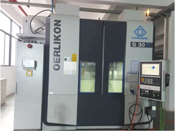
The platform for this technological adaptation is the H120C, a 6-axis CNC spiral bevel gear milling machine originally designed for finishing small spiral bevel gears. Its inherent flexibility and high dynamic performance made it an ideal candidate. The machine’s core axes include three linear axes (X, Y, Z) and three rotary axes (A: workpiece, B: workpiece tilt, C: tool spindle). For our straight bevel gear milling application, we primarily utilize the synchronized motion of the C-axis (hob rotation), A-axis (workpiece rotation for indexing), and coordinated linear motions of the X and Z axes to achieve the compound feed path. The machine’s compact rigidity and high spindle speed capability (up to 3500 RPM for the C-axis) are perfectly suited for high-speed machining with small-diameter carbide hobs. The key specifications of the H120C platform are summarized below.
| Parameter Category | Parameter | Value |
|---|---|---|
| Workpiece Capacity | Maximum Gear Outer Diameter | 120 mm |
| Maximum Module | 4 mm | |
| Maximum Face Width | 30 mm | |
| Number of Teeth Range | 1 – 200 | |
| Tool Spindle | Maximum Speed (C-axis) | 3500 rpm |
| Tool Arbor Interface | Specific to hob shank | |
| Power | Sufficient for carbide milling | |
| Linear Axes Travel | X-axis | ±210 mm |
| Y-axis | -100 to +45 mm | |
| Z-axis | -25 to +240 mm | |
| Rotary Axes | A-axis (Workpiece) Speed | 0 – 200 rpm |
The success of this project hinged on the development of a dedicated CNC program module for straight bevel gear milling. We created a parametric programming system where the operator inputs the gear blank data, hob parameters, and fixture offsets. The software then automatically calculates the complex synchronized motion trajectories for all involved axes. This includes the precise coordination of the rotary axes for continuous indexing and the linear axes for the compound feed path, ensuring correct tooth geometry across the entire face width. The algorithm also manages approach and retract motions for safe and efficient cycling. This turnkey software solution transforms the versatile H120C machine into a dedicated high-speed straight bevel gear milling cell with minimal setup time.
Prior to physical trials, a comprehensive digital verification was conducted using VERICUT simulation software. A virtual digital twin of the H120C machine tool was constructed, incorporating accurate 3D models of all machine components, the fixture, the workpiece blank, and the single-position hob. The kinematic chain and axis limits were precisely defined to match the physical machine. The CNC program generated by our dedicated module was then run in this virtual environment. The simulation allowed us to visually verify the entire gear milling process in real-time, checking for any potential collisions between the tool, tool holder, workpiece, or machine elements. Furthermore, the simulation provided a material removal analysis, confirming the correctness of the tool path and ensuring the final virtual gear model matched the designed tooth form. This step was crucial for de-risking the process and validating the post-processor logic before any metal was cut.
Following successful simulation, physical machining trials were conducted. The test gear pair had the following parameters: Pinion Teeth: 37, Gear Teeth: 74, Module: 0.5 mm, Pressure Angle: 20°, Face Width: 5 mm. A carbide-tipped single-position hob with a diameter of 25.4 mm was used. The process parameters were optimized for high-speed gear milling.
| Parameter | Value |
|---|---|
| Hob Spindle Speed (C-axis) | 1500 rpm |
| Plunge Feed Rate | Optimized for tool engagement |
| Rolling Feed Rate | Optimized for surface finish |
| Coolant | High-pressure flood coolant |
The results were immediately apparent in terms of cycle time. A direct comparison was made against the traditional method of machining the same gear pair on a conventional mechanical gear planing machine (exemplified by models like the HARBECK 12H). The efficiency gain from continuous high-speed gear milling was dramatic.
| Component | H120C Gear Milling Time | Conventional Planing Machine Time | Time Reduction |
|---|---|---|---|
| Gear (74 Teeth) | 6 minutes | 60 minutes | 90% (to 10%) |
| Pinion (37 Teeth) | 6 minutes | 45 minutes | 86.7% (to 13.3%) |
The dramatic reduction in machining time, down to just 10-13.3% of the conventional planing time, unequivocally demonstrates the high-efficiency potential of this gear milling process. However, gains in speed are meaningless without precision. The machined gears were subjected to rigorous inspection on a gear measuring center (e.g., Klingelnberg P series or similar). The primary evaluation criteria were pitch accuracy and tooth flank form deviation. Pitch accuracy was evaluated according to DIN standards, measuring parameters such as single pitch deviation ($f_p$) and total cumulative pitch deviation ($F_p$). The flank form error was assessed by comparing the measured tooth surface against the theoretical conjugate tooth surface model.
The inspection data confirmed that the high-speed process did not compromise quality. The pitch accuracy for both the gear and pinion consistently achieved levels equivalent to DIN class 4, which is suitable for many precision applications. Furthermore, the maximum deviation between the actual machined flank and the theoretical flank was found to be less than 7.5 μm across the entire active profile. This level of form accuracy, combined with the exceptional pitch precision, validates that the high-speed gear milling process is capable of producing functionally excellent gears. The relationship between feed, speed, and resulting error can be modeled for optimization. For instance, the theoretical form error $\epsilon_{form}$ at a point on the tooth is a complex function of the hob geometry, machine kinematics, and gear parameters, but the overall process capability is proven empirically:
$$ \epsilon_{form}(actual) < 7.5 \mu m $$
$$ F_p \leq \text{Limit for DIN 4} $$
| Quality Metric | Measured Result | Target / Standard |
|---|---|---|
| Single Pitch Deviation ($f_p$) | Within tolerance band | DIN 4 |
| Total Cumulative Pitch Deviation ($F_p$) | Within tolerance band | DIN 4 |
| Maximum Tooth Flank Form Error | < 7.5 μm | Application-specific (Met) |
In conclusion, this project has successfully demonstrated a transformative approach to machining small module straight bevel gears. By adapting a high-performance CNC spiral bevel gear milling platform and developing specialized software for continuous hobbing-milling kinematics, we have established a process that dramatically increases productivity. The key outcomes are: 1) The implementation of a dedicated high-speed gear milling cycle on a modified CNC machine, enabling the use of efficient carbide cutting tools. 2) A cycle time reduction of approximately 87-90% compared to conventional planing methods for the tested gear pair. 3) The maintenance of high geometric accuracy, with pitch quality achieving DIN class 4 and tooth flank errors under 7.5 μm. This synergy of speed and precision addresses a significant industry need. The process is particularly advantageous for small-to-medium batch production of precision straight bevel gears, offering a compelling alternative to slower generating methods or capital-intensive mass-production techniques. The methodology outlined—combining machine tool adaptation, dedicated software, virtual verification, and parameter optimization—provides a blueprint for implementing efficient, high-precision gear milling solutions for other challenging gear geometries.