
The pursuit of high-efficiency and high-precision manufacturing for small module straight bevel gears is a persistent theme in modern gear production. Traditional methods, such as gear planing, often suffer from inherent limitations in cycle times due to their intermittent, single-tooth indexing nature. This article details a research and development effort focused on implementing a continuous high-speed hob-milling process for small module straight bevel gears. The core of this work involves adapting a multi-axis CNC spiral bevel gear milling machine for this purpose, developing the corresponding NC programming logic, and rigorously validating the process through simulation and physical machining trials. The term ‘gear milling‘ in this context specifically refers to the continuous generating and forming action achieved by a rotating hob, distinguishing it from conventional planing or face milling.
1. Principle of Hob-Milling for Straight Bevel Gears
The hob-milling process for straight bevel gears is fundamentally a form-cutting method utilizing a special type of tool known as a single-position or fixed-setting hob. Unlike generating hobs for cylindrical gears, this hob is designed to approximate the tooth profile of the gear at its large end. The machining kinematics are characterized by two principal motions: a continuous rotational motion of the hob (C-axis) and a synchronized continuous rotation of the workpiece (A-axis), maintaining a fixed speed ratio defined by the number of teeth on the gear. This continuous indexing is a key factor enabling high-speed gear milling.
To complete the tooth slot, two additional linear feed motions are required. The first is an infeeding motion perpendicular to the pitch cone element, bringing the tool from the gear’s outer diameter to the full tooth depth. The second is a traversing motion along the direction of the pitch cone element to machine the entire face width of the gear. The basic process sequence and the tool-workpiece relationship can be described by the following coordinate transformation. Let the machine coordinate system be (X, Y, Z), and the workpiece coordinate system be defined relative to its pitch cone. The tool center point (TCP) path is calculated to follow these two linear segments while maintaining the correct rotational synchronization.
The fixed-setting hob typically has a multi-tooth design with staggered cutting edges (e.g., 5 or 7 teeth) to balance cutting forces. Its tooth profile is not a true involute but is often approximated by circular arcs corresponding to the theoretical involute at the gear’s large end on the developed back cone. This approximation introduces a profile deviation that increases toward the toe (small end) of the gear. The acceptability of this error is governed by the following condition: for small module gears (face width < 25% of the outer cone distance), the deviation’s impact on meshing performance is minimal. The basic kinematic relationship is:
$$ \frac{N_c}{N_a} = \frac{Z_w}{K} $$
Where \(N_c\) is the hob spindle speed (C-axis), \(N_a\) is the workpiece spindle speed (A-axis), \(Z_w\) is the number of teeth on the workpiece, and \(K\) is the number of starts on the hob (typically 1).
| Feature | Traditional Planing/Gear Milling | Proposed Hob-Milling/Gear Milling |
|---|---|---|
| Processing Method | Generating (Formative), Single-Tooth Indexing | Form-Cutting, Continuous Indexing |
| Tool | Reciprocating or rotating face cutter | Rotating single-position hob |
| Cutting Motion | Intermittent, with return stroke | Continuous, unidirectional rotation |
| Key Advantage | Accurate theoretical involute profile | Very High Material Removal Rate (MRR) |
| Primary Limitation | Low efficiency due to non-cutting time | Small profile deviation at tooth toe |
2. Adaptation of a CNC Spiral Bevel Gear Milling Machine
The successful implementation of this high-speed gear milling strategy relies on a flexible, multi-axis CNC platform. The H120C CNC spiral bevel gear milling machine serves as an ideal foundation. This machine’s inherent multi-axis capability, designed for complex flank modifications in spiral bevel gears, is repurposed for the coordinated linear and rotary motions required for straight bevel gear hobbling.
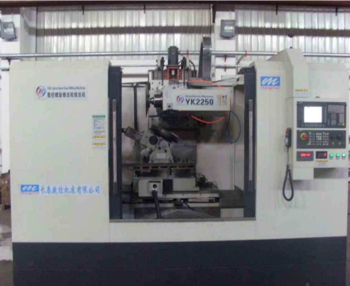
The machine’s configuration includes three linear axes (X, Y, Z) and three rotary axes (A, B, C). For the hob-milling process, the critical axes are:
- A-axis (Workpiece Spindle): Holds the gear blank and provides the continuous indexing rotation.
- C-axis (Tool Spindle): Drives the hob at high rotational speeds.
- B-axis: Used to set the proper angle between the workpiece axis and the tool axis, corresponding to the root angle of the bevel gear.
- X, Y, Z axes: Perform the linear infeeding and traversing motions precisely.
This axis configuration allows the machine to simulate the required tool path relative to the conical workpiece geometry accurately. The NC program synchronizes A and C-axis rotation while linearly interpolating the X, Y, Z axes along the predefined path. Key machine parameters relevant to small module gear milling are summarized below:
| Parameter Category | Parameter | Specification |
|---|---|---|
| Workpiece Capacity | Maximum Gear Diameter | 120 mm |
| Maximum Module | 4 mm | |
| Maximum Face Width | 30 mm | |
| Spindle Speeds | Workpiece Spindle (A-axis) | 0 – 200 rpm |
| Tool Spindle (C-axis) | 0 – 3500 rpm | |
| Travel Range | Linear Axes (X, Y, Z) | ±210 mm, 145 mm, 265 mm |
| Rotary Axis (B) | -95° to +95° |
3. Development and Simulation of the NC Gear Milling Process
A dedicated software module was developed to generate the NC code for the hob-milling process. The module requires inputs such as gear geometric parameters (teeth number, module, pressure angle, face width, pitch angle), tool parameters (diameter, number of teeth, spiral angle), and setup parameters (blank position, offset values). It calculates the precise tool center point trajectory, synchronizes the axes, and outputs a standard G-code program.
To validate the correctness of the NC program and to prevent potential collisions, a virtual machining environment was constructed using VERICUT software. This involved:
- Machine Modeling: Creating 3D models of all machine components (base, columns, spindles, slides) and defining their kinematic chain according to the H120C’s topology.
- Tool Modeling: Importing the precise 3D model of the carbide-tipped single-position hob, including its holder.
- Workpiece and Fixture Modeling: Defining the gear blank and its fixture.
- Process Simulation: Loading the generated NC program and running the virtual machine. VERICUT simulates material removal in real-time.
The simulation confirmed the absence of collisions and verified that the tool path correctly produced the conical gear shape. The virtual gear milling process served as a crucial proof-of-concept, de-risking the subsequent physical trials.
4. Physical Machining and Performance Analysis
Following successful simulation, physical machining trials were conducted on the H120C machine. A gear pair with the following specifications was chosen for verification: Pinion teeth (Z1) = 37, Gear teeth (Z2) = 74, Module (m) = 0.5 mm, Pressure angle (α) = 20°, Face width = 5 mm. A carbide-coated single-position hob with a diameter of 25.4 mm was used at a spindle speed of 1500 rpm.
The most significant result was the dramatic reduction in cycle time. Compared to machining the same gear pair on a conventional mechanical planing machine (e.g., a HARBECK 12H), the hob-milling process demonstrated superior efficiency.
| Component | Hob-Milling Time (H120C) | Planing Time (12H Machine) | Efficiency Gain |
|---|---|---|---|
| Gear (74 teeth) | 6 minutes | 60 minutes | ~90% reduction (10% of planing time) |
| Pinion (37 teeth) | 6 minutes | 45 minutes | ~86.7% reduction (~13.3% of planing time) |
The quality of the machined gears was evaluated on a precision gear measuring center (L65G). The primary metrics were pitch accuracy and flank form deviation. The pitch accuracy, including single pitch deviation (f_p) and total cumulative pitch deviation (F_p), achieved levels equivalent to DIN class 4, indicating excellent indexing accuracy from the continuous CNC-controlled A-axis. The flank form error, which measures the deviation between the actual machined surface and the theoretical involute surface, was found to be within a tight tolerance band. The maximum observed form error was 7.4 μm, which is highly acceptable for small module gears. The form error \( \Delta F_{\alpha} \) at any point on the flank can be conceptualized as:
$$ \Delta F_{\alpha}(s) = Z_{actual}(s) – Z_{theoretical}(s) $$
where \( s \) is the trace length along the profile evaluation line, and \( Z \) represents the surface coordinate. The measured values confirmed that the approximation inherent in the fixed-setting hob design was well within functional limits for the target application.
| Measurement | Gear (74 Teeth) | Pinion (37 Teeth) | Standard/Grade |
|---|---|---|---|
| Single Pitch Deviation (f_p) | Within tolerance band | Within tolerance band | DIN 4 |
| Total Pitch Deviation (F_p) | Within tolerance band | Within tolerance band | DIN 4 |
| Max Profile Form Error | 5.4 μm | 7.4 μm | N/A |
5. Summary and Conclusions
This work successfully demonstrates the feasibility and advantages of high-speed hob-milling for small module straight bevel gears on a modified CNC spiral bevel gear milling machine. By developing a specialized NC programming solution and leveraging the machine’s multi-axis capabilities, a continuous, form-cutting process was implemented. The VERICUT simulation provided essential validation of the tool paths and process kinematics before physical cutting. The actual machining results proved the concept decisively: achieving a gear quality of DIN 4 in pitch accuracy with minimal form errors, while reducing machining time to merely 10-13.3% of that required by traditional planing methods. This approach represents a significant advancement in the productive gear milling of small module straight bevel gears, offering a compelling solution for applications demanding both high volume and high precision.