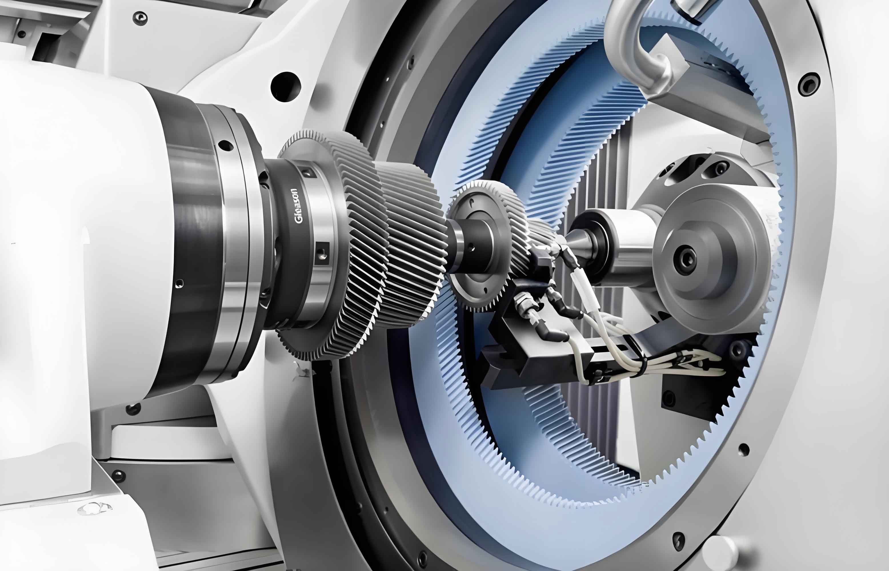
High-precision modified gears are critical for high-performance transmission systems in industrial robots and new energy vehicles. Hobbing enables efficient roughing/semi-finishing of cylindrical gears, while gear honing offers high efficiency and superior surface quality in finishing. Synergistic hobbing-honing integration enhances both precision and productivity. However, uneven residual allowances from hobbing adversely affect gear honing accuracy, efficiency, and tool life due to inherent differences in tooth-surface generation mechanisms. This study establishes mathematical models for hobbing and gear honing processes, proposes a multi-axis linkage-based pre-modification method for hobbing, and optimizes honing allowances through sensitivity analysis and dynamic programming.
Mathematical Modeling of Hobbing and Gear Honing Processes
The kinematic relationship for hobbing involves synchronized rotation of the hob and workpiece with axial feed. The hob-workpiece center distance \(a\) and shaft angle \(\Sigma\) are defined as:
$$
a = r_g \pm r_h, \quad \Sigma = \beta_g – \beta_h
$$
where \(r_g\) and \(r_h\) are pitch radii, \(\beta_g\) and \(\beta_h\) are spiral angles. Coordinate systems and homogeneous transformations derive the hobbed tooth surface \(\mathbf{r}_g(u, v, \phi_h, \zeta)\):
$$
\mathbf{r}_g = \mathbf{M}_{g1} \cdot \mathbf{M}_{12} \cdot \mathbf{M}_{23} \cdot \mathbf{r}_h
$$
Gear honing employs an internal honing wheel meshing with the workpiece under crossed axes. Key parameters include center distance \(a_1\) and shaft angle \(\Sigma_1\):
$$
a_1 = r_g \pm r_{hn}, \quad \Sigma_1 = \beta_g – \beta_{hn}
$$

The honed tooth surface \(\mathbf{r}_{g1}\) is derived via coordinate transformations:
$$
\mathbf{r}_{g1} = \mathbf{M}_{g14} \cdot \mathbf{M}_{45} \cdot \mathbf{M}_{56} \cdot \mathbf{r}_{hn}
$$
Hobbing Pre-Modification via Multi-Axis Linkage
Pre-modification during hobbing compensates for honing distortions. Radial feed (\(Y\)-axis) and hob tilt (\(B\)-axis) motions are synchronized using quadratic polynomials:
$$
a_i = a + b_0 + b_1 \zeta + b_2 \phi_h + b_3 \zeta^2 + b_4 \phi_h^2 + b_5 \zeta \phi_h
$$
$$
\Sigma_i = \Sigma + b_6 + b_7 \zeta + b_8 \phi_h + b_9 \zeta^2 + b_{10} \phi_h^2 + b_{11} \zeta \phi_h
$$
where \(b_0\)–\(b_{11}\) are modification parameters. The normal honing allowance \(h_i\) at grid points is:
$$
h_i = \left( \mathbf{r}_{gi}^m – \mathbf{r}_{gi} \right) \cdot \mathbf{n}_{gi}
$$
A sensitivity matrix \(\mathbf{H}\) quantifies parameter influences:
$$
\mathbf{H} = \begin{bmatrix}
\frac{\partial h_1}{\partial b_0} & \cdots & \frac{\partial h_1}{\partial b_{11}} \\
\vdots & \ddots & \vdots \\
\frac{\partial h_{35}}{\partial b_0} & \cdots & \frac{\partial h_{35}}{\partial b_{11}}
\end{bmatrix}
$$
Table 1 shows sensitivity coefficients for a case study (module = 2 mm, helix angle = 25°).
| Grid Point | \(\partial h / \partial b_3\) | \(\partial h / \partial b_{10}\) |
|---|---|---|
| 1 | 4.5434 | 0.5987 |
| 5 | 80.1743 | 154.1191 |
| 35 | -141.3172 | 110.7018 |
Higher-order terms (\(b_3\)–\(b_5\), \(b_9\)–\(b_{11}\)) exhibit greater influence than linear terms, with \(B\)-axis parameters dominating \(Y\)-axis effects.
Hobbing-Honing Synergy and Allowance Control
The target honing allowance \(h_{1i}\) is calculated from deviations between hobbed and honed surfaces:
$$
h_{1i} = \left( \mathbf{r}_{g1i}^m – \mathbf{r}_{gi} \right) \cdot \mathbf{n}_{gi}
$$
Modification parameters are solved via singular value decomposition (SVD) of \(\mathbf{H}\):
$$
\mathbf{H} = \mathbf{U} \cdot \mathbf{\Sigma} \cdot \mathbf{V}^T, \quad \Delta \mathbf{b} = \mathbf{V} \cdot \mathbf{\Sigma}^+ \cdot \mathbf{U}^T \Delta \mathbf{h}
$$
Dynamic programming optimizes \(\Delta \mathbf{b}\) over decision stages \(n\):
$$
\begin{aligned}
&\text{Minimize} \quad C_n = \sum_{1 \leq i \leq n} c_i(r_i, l_i) \\
&c_i = \sum_{j=1}^{35} \left| \left( \mathbf{r}_{gij}^m – \mathbf{r}_{gij} \right) \cdot \mathbf{n}_{gij} \right|
\end{aligned}
$$
Table 2 compares allowance uniformity before/after optimization for three honing profiles.
| Case | Method | Max Error (mm) | Mean Error (mm) | Variance |
|---|---|---|---|---|
| 1 | Sensitivity Matrix | 0.4023 | 0.0291 | 9.9e-4 |
| Dynamic Programming | 0.0092 | 0.0023 | 1.1e-5 | |
| 2 | Sensitivity Matrix | 0.1701 | 0.0979 | 7.4e-4 |
| Dynamic Programming | 0.0084 | 0.0039 | 1.9e-5 | |
| 3 | Sensitivity Matrix | 0.1275 | 0.1110 | 5.7e-5 |
| Dynamic Programming | 0.0092 | 0.0034 | 1.7e-5 |
Optimization reduces maximum error by 95–98% and variance by 88–99%, ensuring uniform gear honing allowances.
Virtual Simulation Machining
A VERICUT-based virtual hobbing platform validates the methodology. A 5-axis CNC hobbing machine model (Figure 3) integrates:
- Radial feed (\(Y\)), axial feed (\(Z\)), and tangential feed (\(X\)) axes
- Hob rotation (\(A\)), tilt (\(B\)), and workpiece rotation (\(C\))
Simulated gear honing allowances after virtual hobbing show ≤0.0337 mm deviation from targets (Table 3), aligning with numerical predictions.
| Point | Deviation (mm) | Coordinates (x, y, z) (mm) |
|---|---|---|
| 4 | 0.0337 | (-33.47, -0.35, 2.4) |
| 11 | 0.0229 | (-34.53, -0.65, 2.4) |
| 32 | -0.0307 | (-38.90, -3.10, 2.4) |
Conclusion
This study establishes a synergistic hobbing-honing framework for precision gear manufacturing. Key contributions include:
- Mathematical models for hobbing and gear honing tooth-surface generation.
- A multi-axis linkage strategy enabling hobbing pre-modification via \(Y\)/\(B\)-axis quadratic motion functions.
- Dynamic programming optimization of modification parameters, reducing honing allowance variance by >88%.
- Virtual verification confirming ≤0.0337 mm allowance deviations.
The methodology ensures uniform gear honing allowances, enhancing process efficiency and tool life. Future work will incorporate higher-order polynomials and machine-tool dynamics.
