
In my first-person evaluation of axle gear manufacturing, I treat accuracy as the final result of a chain of thermal and mechanical events rather than as a single machining outcome. The axle gear must transmit torque smoothly, resist bending and contact fatigue, and maintain a stable mesh under road load. When I examine a failed or noisy axle gear, I rarely find that one isolated operation is responsible. Instead, I usually find that material quality, the condition of the forged gear blank, preliminary heat treatment, carburizing, quenching, and tempering have combined to shift tooth geometry outside the intended class. For automotive axle gears, I normally work toward accuracy classes comparable to grade 7 to 8 in recognized bevel gear accuracy systems, because this range balances manufacturing cost with acceptable motion error, noise, and load distribution. A forged gear blank that is inconsistent in hardness, banding, grain size, or internal stress can create a machining pattern that looks acceptable before heat treatment but becomes unacceptable after final hardening. Therefore, I begin every accuracy investigation at the thermal processing chain.
My central observation is that hot processing affects gear accuracy through three coupled mechanisms. The first mechanism is thermal strain caused by non-uniform heating and cooling. The second is transformation strain caused by phase changes, especially the austenite-to-martensite transformation during quenching. The third is mechanical constraint and residual stress interaction between the fixture, the forged gear blank geometry, and the cooling medium. I summarize these contributions with a distortion vector:
$$ \mathbf{d}_{total} = \mathbf{d}_{thermal} + \mathbf{d}_{transformation} + \mathbf{d}_{stress} + \mathbf{d}_{fixture} $$
Each term can vary with position, time, and local microstructure. In my experience, the most difficult part is that these terms do not simply add in a linear way. A forged gear blank with a slightly banded microstructure may show little distortion after normalizing, yet after carburizing it may show a repeatable but unwanted tooth-to-tooth variation. I therefore monitor the entire route from raw bar to finished tooth flank, and I use the term forged gear blank deliberately because the forged gear blank is the physical carrier of prior thermal history. If the forged gear blank is not uniform, the later carburizing process cannot fully correct it.
The table below summarizes the hot processing stages I consider when I want to improve axle gear accuracy.
| Stage | Primary accuracy risk | Measurable effect on gear | My control focus |
|---|---|---|---|
| Raw material selection | Segregation, inclusions, grain coarsening, hardenability scatter | Irregular distortion after quenching, pitting initiation, tooth breakage | Chemistry, hardenability, grain size, banding, inclusion rating |
| Forging of the forged gear blank | Incomplete deformation, internal cracks, flow line defects, residual stress | Asymmetric tooth growth, runout, position error | Billet heating, die temperature, deformation ratio, cooling after forging |
| Normalizing or isothermal normalizing of the forged gear blank | Hardness scatter, mixed microstructure, banding, retained stress | Poor machinability, variable cutting force, unstable flank finish | Heating zone temperatures, equalization, controlled cooling, equalization temperature |
| Machining before carburizing | Residual cutting stress, inadequate stock allowance | Tooth thickness shift, profile slope, lead variation | Tool condition, fixture rigidity, allowance for heat treatment growth |
| Carburizing and diffusion | Carbon profile variation, case depth scatter, grain growth | Distortion, hardness variation, retained austenite variation | Carbon potential, temperature, time, atmosphere uniformity |
| Quenching | Non-uniform cooling, vapor blanket, fixture constraint | Conicity, ovality, tooth twist, pitch error | Quenchant condition, agitation, loading pattern, transfer time |
| Tempering | Incomplete stress relief, secondary hardening variation | Dimensional instability, reduced fatigue resistance | Temper temperature, time, uniform circulation |
| Final inspection | Late detection of drift | Scrap, rework, assembly noise | SPC, gear measuring center, metallographic verification |
I use the following general distortion index when I compare different thermal routes for a forged gear blank:
$$ D = \sqrt{\frac{F_{\alpha}^{2} + F_{\beta}^{2} + F_{p}^{2}}{3}} $$
Here, \(F_{\alpha}\) represents profile error, \(F_{\beta}\) represents lead error, and \(F_{p}\) represents cumulative pitch error. I prefer this composite index because it prevents me from optimizing one gear accuracy parameter while silently worsening another. In my work, a process change that reduces lead variation but increases profile slope is not a true improvement. The axle gear must satisfy the complete accuracy specification, not a single line on a inspection report.
I also use a simple residual stress balance condition when I evaluate whether a forged gear blank and its heat treatment are likely to remain stable:
$$ \int_{A} \sigma(z)\,dA = 0 $$
$$ \int_{A} z\,\sigma(z)\,dA = 0 $$
These equations remind me that residual stress cannot simply disappear. It redistributes. If I remove material from one side of a forged gear blank during machining, the balance changes and the gear may move during subsequent heating. If I quench a forged gear blank asymmetrically, the balance changes again. The final tooth geometry is therefore the visible expression of an invisible stress state. I have found that this concept is essential when I explain why a gear that measured well before carburizing can fail accuracy after quenching.
The influence of raw material quality is often underestimated. In my experience, the selection of steel for axle gears should not be based only on nominal hardness or strength. I look at hardenability, grain size, banding, non-metallic inclusion content, and alloy segregation. A forged gear blank made from steel with severe banding may machine without obvious problems, but during carburizing the bands respond differently to austenitizing and quenching. The result can be a wavy tooth profile or a lead error that varies along the face width. Table 2 lists the raw material factors I check and the mechanisms through which they affect final gear accuracy.
| Material factor | Why I check it | Influence on forged gear blank | Final gear accuracy risk |
|---|---|---|---|
| Grain size | Coarse grains reduce toughness and create stress concentration | Non-uniform deformation during forging and heat treatment | Higher distortion scatter, lower fatigue life |
| Banding | Banding indicates chemical segregation, especially phosphorus and alloy elements | Anisotropic response to normalizing and quenching | Tooth-to-tooth variation, profile waviness |
| Non-metallic inclusions | Inclusions break matrix continuity | Local stress raisers in the forged gear blank | Pitting, cracking, unpredictable distortion |
| Hardenability | Controls depth and distribution of martensite | Different hardness through the forged gear blank section | Case-core mismatch, ovality, size change |
| Carbon content | Controls core strength and response to carburizing | Variation in thermal expansion and transformation strain | Pitch error, tooth thickness scatter |
| Alloy segregation | Creates local transformation differences | Non-uniform austenite stability in the forged gear blank | Retained austenite variation, grinding cracks |
| Initial residual stress | Carries forward into machining and heat treatment | Movement after material removal | Lead and profile drift |
I use a simple expression for thermal strain when I estimate the first-order size change of a forged gear blank:
$$ \varepsilon_{th} = \alpha \Delta T $$
For steel, the coefficient of thermal expansion \(\alpha\) is on the order of \(11 \times 10^{-6}\) to \(13 \times 10^{-6}\ \mathrm{K^{-1}}\), depending on temperature and microstructure. This means that a temperature difference of \(100\ \mathrm{K}\) across a forged gear blank can produce a thermal strain of approximately \(0.0011\) to \(0.0013\). If the forged gear blank is constrained or if the temperature field is not uniform, the resulting stress can exceed the yield strength at high temperature and cause plastic deformation. I therefore pay close attention to preheating, equalization, and fixture design before quenching.
Transformation strain is even more important during quenching. When austenite transforms to martensite, the volume increases. I represent the total transformation strain as a weighted sum over phases:
$$ \varepsilon_{tr} = \sum_{i} f_{i} \varepsilon_{i} $$
Here, \(f_{i}\) is the volume fraction of phase \(i\), and \(\varepsilon_{i}\) is its transformation strain. Because martensite has a larger specific volume than austenite, the local expansion can be significant. If different regions of the forged gear blank transform at different times, the gear distorts. This is why I insist on uniform austenitizing and controlled cooling. The forged gear blank must enter the quench with a uniform temperature and a uniform austenite condition, or the transformation strain will be non-uniform.
I also evaluate the cooling rate because it controls both microstructure and stress. A simplified cooling rate expression is:
$$ v_{c} = \frac{T_{initial} – T_{final}}{t_{c}} $$
If \(v_{c}\) is too low, I may fail to form the desired martensitic case. If \(v_{c}\) is too high or non-uniform, I may create excessive thermal shock and cracking. In my experience, the best quench is not the fastest quench. It is the quench that produces the required hardness and case depth with the most uniform cooling field across the forged gear blank. This is why I treat agitation, quenchant temperature, polymer concentration, and load orientation as accuracy variables, not just hardness variables.
Forging is the stage where the forged gear blank acquires its initial flow lines, grain flow, and internal stress pattern. I have seen many cases where a forged gear blank appeared acceptable after forging and normalizing, but later showed a repeatable lead error after carburizing. The root cause was often an asymmetric forging sequence or a cooling practice that produced different microstructures on opposite sides of the forged gear blank. When I audit forging, I look at billet heating, die lubrication, deformation speed, flash formation, and post-forging cooling. I also verify that the forged gear blank has enough stock for machining and that the flow lines are favorable for tooth root strength.
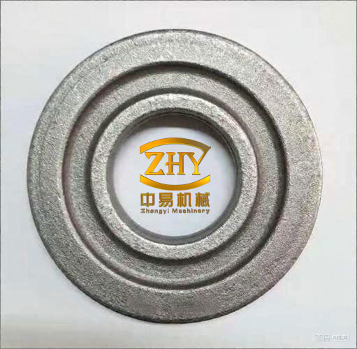
After forging, I consider normalizing or isothermal normalizing to be the most important preparatory heat treatment for the forged gear blank. The purpose is not merely to reduce hardness. The purpose is to create a uniform, fine, and stable microstructure that machines consistently and responds predictably to carburizing. If the forged gear blank has banded or mixed microstructure, the machining force changes from tooth to tooth, and the cutting tool may leave different residual stress patterns. Those patterns then interact with carburizing and quenching, producing tooth-to-tooth accuracy scatter. I therefore treat the forged gear blank as a thermal component that must be normalized before it becomes a precision gear.
Isothermal normalizing is especially useful because it separates the austenitizing stage from the transformation stage. Instead of cooling continuously through a wide temperature range, I austenitize the forged gear blank, equalize it, and then transfer it to a controlled temperature zone where transformation occurs at a nearly constant temperature. This produces a more uniform ferrite-pearlite structure and reduces the risk of bainite or martensite formation. It also improves hardness uniformity, which directly improves machining accuracy. In my experience, a well-controlled isothermal normalizing process can reduce hardness scatter across a batch and make the forged gear blank much more predictable during subsequent tooth cutting.
The table below shows a representative isothermal normalizing window I have used as a reference for a 20CrMnTi-type forged gear blank. I adjust the exact values according to section size, furnace capability, and quenchant characteristics.
| Parameter | Reference value | Purpose | Risk if uncontrolled |
|---|---|---|---|
| Heating zone 1 temperature | 930 °C | Start austenitizing the forged gear blank | Incomplete transformation, residual ferrite |
| Heating zone 2 temperature | 940 °C | Complete austenitizing and homogenization | Grain growth, overheating |
| Heating zone 3 temperature | 940 °C | Equalize temperature through the forged gear blank | Non-uniform transformation |
| Equalization temperature | 500 °C | Controlled isothermal transformation | Bainite, hardness scatter |
| Forced air temperature | 300 °C | Accelerate initial cooling before equalization | Insufficient cooling, coarse pearlite |
| Forced air time | 12 s | Control cooling path | Too short or too long changes microstructure |
| Strong air time | 100 s | Stabilize cooling rate | Non-uniform hardness |
| Upward blow time | 45 s | Improve cooling uniformity | Top-to-bottom hardness difference |
| Downward blow time | 40 s | Improve cooling uniformity | Side-to-side hardness difference |
| Blowing cycles | 8 | Control repeated air exchange | Temperature fluctuation |
| Pushing period | 1200 s | Maintain furnace rhythm | Residence time scatter |
| Target hardness | 165–175 HBW | Good machinability | Tool wear or built-up edge |
| Same-piece hardness range | ≤5 HBW | Uniform response within one forged gear blank | Distortion after carburizing |
| Same-batch hardness range | ≤10 HBW | Batch consistency | Process drift, scrap |
| Microstructure | Uniform ferrite + pearlite | Predictable machining and heat treatment | Banding, mixed structure, erratic distortion |
| Bainite | None or very little | Avoid hard spots | Poor machinability, distortion |
| Grain size | 5–8 ASTM | Balanced strength and toughness | Coarse grains reduce fatigue life |
| Banding level | 0–3 | Limit segregation effects | Anisotropic distortion |
I use hardness uniformity as a quick indicator of whether the forged gear blank is ready for precision machining:
$$ HU = \max(H_{i}) – \min(H_{i}) $$
If \(HU\) is large within one forged gear blank, I know that the cutting force will vary as the tool moves around the gear. The tool will deflect differently, and the resulting tooth profile will carry a hidden error that may only appear after carburizing. I therefore reject or re-normalize forged gear blanks that show excessive hardness scatter. In my experience, spending extra effort on the forged gear blank before machining is far cheaper than correcting distortion after carburizing.
Overheating during normalizing is particularly damaging. If the forged gear blank is heated too high for too long, the austenite grain size grows. Even if I later apply a normal normalizing cycle, the coarse grain structure may not be fully refined. The material loses toughness, fatigue resistance, and crack growth resistance. In severe cases, the forged gear blank develops internal cracks that are difficult to detect before machining. These cracks can later open during quenching or in service. I therefore set upper temperature limits and verify furnace uniformity regularly. I also use metallographic inspection to confirm that the forged gear blank has a fine, uniform structure rather than an overheated one.
Carburizing is the next major hot processing step that affects gear accuracy. In carburizing, I hold the forged gear blank at an elevated temperature in a carbon-rich atmosphere so that carbon diffuses into the surface. The carbon profile can be approximated by a diffusion solution:
$$ C(x,t) = C_{s} – \left(C_{s} – C_{0}\right) \mathrm{erf}\left(\frac{x}{2\sqrt{Dt}}\right) $$
Here, \(C_{s}\) is the surface carbon potential, \(C_{0}\) is the initial carbon content, \(D\) is the diffusion coefficient, \(x\) is depth, and \(t\) is time. The diffusion coefficient depends strongly on temperature:
$$ D = D_{0} \exp\left(-\frac{Q}{RT}\right) $$
Because \(D\) increases rapidly with temperature, small furnace temperature differences can produce measurable case depth differences. If one side of the forged gear blank sees a higher temperature or a higher carbon potential, that side may develop a different case depth and a different transformation behavior. The result is a gear that conforms to one accuracy class in one region and a poorer class in another. I therefore treat carburizing atmosphere uniformity, temperature uniformity, and loading pattern as accuracy controls. The forged gear blank must be positioned so that the carburizing gas can flow uniformly around every tooth.
The table below lists the carburizing and quenching variables I monitor and their effects on axle gear accuracy.
| Variable | Preferred practice | Effect on forged gear blank | Effect on final gear accuracy |
|---|---|---|---|
| Carburizing temperature | Uniform, within a narrow band | Controls carbon diffusion and grain growth | Case depth scatter, distortion |
| Carbon potential | Controlled and stable | Controls surface carbon and carbide formation | Retained austenite, hardness variation |
| Diffusion time | Optimized for case depth | Determines carbon profile | Tooth size growth, residual stress |
| Furnace atmosphere circulation | High uniformity around every tooth | Prevents local carbon variation | Tooth-to-tooth profile error |
| Fixture and loading | Rigid, symmetric, minimal masking | Controls heat transfer and gas access | Lead variation, ovality |
| Quench transfer time | As short and repeatable as possible | Prevents premature transformation | Hardness scatter, distortion |
| Quenchant temperature | Controlled within a narrow range | Controls cooling rate | Cracking, size change |
| Agitation | Uniform and sufficient | Breaks vapor blanket | Soft spots, non-uniform distortion |
| Quenchant concentration | Maintained by daily checks | Controls cooling speed | Case-core mismatch, cracking |
| Post-quench tempering | Immediate and uniform | Relieves stress, tempers martensite | Dimensional stability, toughness |
I often use a hardness profile expression to check whether the carburized case is behaving as expected:
$$ HV(x) = HV_{core} + \left(HV_{surface} – HV_{core}\right)\exp\left(-\frac{x}{\lambda}\right) $$
Here, \(\lambda\) is a characteristic depth parameter. If the measured profile deviates from the expected curve, I investigate carbon potential, temperature, time, and quench uniformity. A forged gear blank with a non-uniform case depth will usually show non-uniform tooth growth. This is why I do not separate metallurgical quality from dimensional quality. They are the same problem seen from different perspectives.
Quenching is the most dramatic source of distortion. When the forged gear blank is cooled, the surface cools faster than the core. The surface contracts thermally, then expands as it transforms to martensite, while the core may still be austenitic or may transform later. The result is a complex stress history. I use a simplified total strain expression to keep the main contributions visible:
$$ \varepsilon_{total}(x,t) = \varepsilon_{thermal}(x,t) + \varepsilon_{transformation}(x,t) + \varepsilon_{mechanical}(x,t) $$
If the forged gear blank is not symmetric, or if the quench flow is not symmetric, the strain field becomes asymmetric. The gear may bend, twist, or change lead. In my experience, many lead errors after carburizing are not caused by the cutting machine. They are caused by asymmetric quenching of the forged gear blank. This is why I pay attention to the orientation of the forged gear blank in the fixture, the direction of quenchant flow, and the spacing between parts.
I also consider the effect of retained austenite. Retained austenite is soft compared with martensite, and it can transform later under load or during grinding. If the amount of retained austenite varies from tooth to tooth, the gear may show dimensional instability. I use a simple volume fraction expression when I discuss phase balance:
$$ f_{\gamma} + f_{\alpha’} + f_{c} + f_{other} = 1 $$
Here, \(f_{\gamma}\) is retained austenite, \(f_{\alpha’}\) is martensite, \(f_{c}\) is carbide, and \(f_{other}\) includes ferrite, bainite, and other constituents. In my experience, a controlled amount of retained austenite can improve fatigue resistance, but excessive or non-uniform retained austenite is harmful. I therefore specify limits and verify them metallographically. A forged gear blank with excessive retained austenite may measure acceptably after cooling but continue to move during storage, grinding, or service.
I have found that tempering is not merely a final softening step. It is a stress-relief and stabilization step. When I temper immediately after quenching, I reduce the risk of delayed cracking and improve dimensional stability. The tempering temperature and time must be uniform throughout the forged gear blank. If the furnace has cold spots, some regions remain under higher residual stress. Later machining or service loading can then trigger distortion or cracking. I therefore validate tempering furnace uniformity and use load thermocouples where possible.
I use the following relationship to estimate the approximate thermal stress generated by a temperature gradient across a forged gear blank:
$$ \sigma_{th} \approx \frac{E \alpha \Delta T}{1 – \nu} $$
Here, \(E\) is Young’s modulus, \(\alpha\) is the thermal expansion coefficient, \(\Delta T\) is the temperature difference, and \(\nu\) is Poisson’s ratio. This expression is simplified, but it helps me explain why rapid cooling of a thick forged gear blank is more dangerous than rapid cooling of a thin, symmetric part. It also explains why preheating and equalization before quenching are so important. If I reduce \(\Delta T\) before the quench, I reduce the thermal stress that drives distortion.
The mechanical behavior of the gear tooth under load is also connected to hot processing. Contact stress and bending stress are influenced by case depth, core hardness, residual stress, and microstructure. I use the Hertzian contact stress expression as a first-order check:
$$ \sigma_{H} = \sqrt{\frac{F_{n}}{\pi b} \left( \frac{1-\nu_{1}^{2}}{E_{1}} + \frac{1-\nu_{2}^{2}}{E_{2}} \right) \Big/ \rho} $$
Here, \(F_{n}\) is normal load, \(b\) is face width, \(E_{1}\) and \(E_{2}\) are elastic moduli, \(\nu_{1}\) and \(\nu_{2}\) are Poisson’s ratios, and \(\rho\) is the equivalent radius of curvature. If the forged gear blank has a non-uniform case, the effective load-carrying capacity varies across the tooth. The gear may then show localized contact marks, noise, or early pitting. I use this relationship qualitatively to remind myself that accuracy is not only a geometric issue. It is also a load distribution issue.
The bending stress at the tooth root can be estimated as:
$$ \sigma_{F} = \frac{F_{t}}{b m_{n}} Y_{F} Y_{S} Y_{\beta} $$
Here, \(F_{t}\) is tangential load, \(m_{n}\) is normal module, and the \(Y\) factors account for form, stress concentration, and helix angle. If the forged gear blank has coarse grains or internal defects, the allowable bending stress is reduced. If the heat treatment produces an unfavorable residual stress pattern, the effective bending strength is also reduced. I therefore treat grain refinement and stress control as accuracy and durability measures at the same time.
In my work, I use statistical process control to separate common-cause variation from special-cause variation. The capability index is a useful summary:
$$ C_{pk} = \min\left( \frac{USL – \mu}{3\sigma}, \frac{\mu – LSL}{3\sigma} \right) $$
For axle gear accuracy, I do not rely on a single \(C_{pk}\) value for all parameters. I calculate capability for tooth profile, lead, pitch, runout, and tooth thickness. A process may be capable for pitch but not for lead. I then investigate whether the lead variation is driven by the forged gear blank, the fixture, the cutting process, or the quench. I have found that lead variation is frequently linked to quench uniformity and fixture support, while pitch variation is more often linked to material uniformity and machining setup. Profile variation can come from both.
The table below shows how I link common accuracy defects to hot processing causes and corrective actions.
| Accuracy defect | Likely hot processing cause | What I inspect first | Corrective action |
|---|---|---|---|
| Tooth profile waviness | Banded microstructure in forged gear blank | Raw material banding, normalizing uniformity | Improve steel cleanliness, adjust isothermal normalizing |
| Lead variation along face width | Asymmetric quenching or fixture support | Quench flow, loading pattern, fixture contact | Redesign fixture, balance agitation, rotate part |
| Pitch error scatter | Case depth variation or retained austenite variation | Carburizing atmosphere, temperature uniformity | Recalibrate furnace, improve gas circulation |
| Tooth thickness growth | Transformation strain and retained austenite | Carbon potential, quench rate, tempering | Adjust carbon profile, quench parameters, tempering |
| Runout after heat treatment | Non-uniform heating or cooling of forged gear blank | Furnace loading, support points, quench orientation | Use symmetric loading, preheat, equalize |
| Ovality | Uneven cooling around circumference | Agitation nozzles, part spacing, quenchant flow | Increase uniformity, reduce part clustering |
| Conicity | Top-to-bottom temperature difference | Furnace zone balance, transfer time | Adjust furnace zones, reduce transfer delay |
| Grinding cracks | Excessive retained austenite or high carbon | Case carbon, tempering, grinding parameters | Reduce surface carbon, improve tempering |
| Early pitting | Insufficient case depth or non-uniform case | Diffusion time, temperature, atmosphere | Increase diffusion, verify furnace uniformity |
| Tooth breakage | Coarse grains or internal forging defects | Forging reduction, normalizing, grain size | Improve forging practice, refine grains |
I also use a simple first-order estimate for tooth size change during heat treatment:
$$ \Delta s = s \alpha \Delta T + \Delta s_{p} + \Delta s_{C} $$
Here, \(s\) is the characteristic tooth dimension, \(\Delta s_{p}\) is the transformation-related size change, and \(\Delta s_{C}\) is the size change associated with carburizing and case formation. This equation is not a substitute for measurement, but it helps me decide how much machining allowance to leave. If I leave too little allowance, I cannot correct distortion after heat treatment. If I leave too much, I increase machining time and may remove too much of the hardened case. I therefore optimize allowance based on historical data from the forged gear blank and the specific heat treatment route.
I have learned that the forged gear blank should be treated as a part with its own process signature. Two forged gear blanks made from the same steel can behave differently if they experience different forging temperatures, cooling rates, or normalizing cycles. This is why I trace every forged gear blank through the process. I record steel heat number, forging date, normalizing cycle, hardness, microstructure, machining setup, carburizing cycle, quench parameters, and final accuracy results. When a problem appears, I can compare the suspect forged gear blank with successful ones. Without traceability, I am forced to guess, and guessing is expensive in axle gear manufacturing.
I use the following simple model to describe the effect of case depth on distortion sensitivity:
$$ \delta \propto \frac{\Delta V_{m} f_{m} L^{2}}{t^{2}} $$
Here, \(\delta\) is an approximate distortion magnitude, \(\Delta V_{m}\) is the volume change associated with martensite formation, \(f_{m}\) is the martensite fraction, \(L\) is a characteristic length, and \(t\) is a characteristic thickness. This relationship is qualitative, but it captures two important points. First, thicker sections and larger forged gear blanks are more sensitive to transformation strain. Second, increasing the martensite fraction increases distortion potential. I therefore avoid excessive case depth unless the design requires it, and I design the forged gear blank with as much symmetry as possible.
In my experience, the best accuracy improvement comes from reducing variation, not simply reducing average distortion. If I can make every forged gear blank distort in the same way, I can compensate during machining. But if the distortion varies from part to part, compensation becomes impossible. Therefore, I focus on process repeatability. I want the same forged gear blank geometry, the same normalizing cycle, the same carburizing temperature, the same quench agitation, and the same tempering cycle every time. I use control charts for furnace temperature, carbon potential, quenchant temperature, quenchant concentration, and hardness. When a chart shows a trend, I correct it before it becomes a gear accuracy problem.
The table below presents a control plan I use for hot processing of a forged gear blank intended for axle gear production.
| Control item | Frequency | Method | Action limit |
|---|---|---|---|
| Raw material chemistry | Each heat | Spectrometer, certificates | Outside specification: reject or segregate |
| Hardenability | Each heat or periodic | End quench test | Outside band: adjust process or reject |
| Grain size | Periodic and after normalizing | Metallography | Coarser than target: investigate |
| Banding | Periodic | Metallography | Above limit: improve steel source |
| Forging temperature | Continuous | Pyrometer, furnace control | Outside window: hold or scrap |
| Post-forging cooling | Continuous | Controlled cooling line | Deviation: adjust normalizing |
| Normalizing temperature | Continuous | Thermocouples, furnace survey | Outside band: correct furnace |
| Normalized hardness | Each batch | Brinell hardness | Outside 165–175 HBW: review |
| Microstructure | Each batch or periodic | Microscopy | Bainite, banding, coarse grain: contain |
| Carburizing temperature | Continuous | Thermocouples, survey | Outside band: correct before release |
| Carbon potential | Continuous | Oxygen probe, CO analyzer | Deviation: adjust atmosphere |
| Case depth | Each batch | Microhardness traverse | Outside specification: rework or scrap |
| Surface hardness | Each batch | Rockwell or Vickers | Below minimum: review quench |
| Retained austenite | Periodic | X-ray diffraction or metallography | Above limit: adjust carbon or tempering |
| Quenchant temperature | Continuous | Thermocouple | Outside band: pause and correct |
| Quenchant concentration | Daily | Refractometer or titration | Outside band: adjust |
| Agitation flow | Weekly or per maintenance | Flow check, visual inspection | Blocked nozzle: clean and verify |
| Tempering temperature | Continuous | Thermocouples | Outside band: correct and re-temper |
| Final gear accuracy | Each part or sample | Gear measuring center | Outside class: contain and investigate |
I also rely on heat treatment system assessment principles to verify that the process is under control. I do not treat a furnace as a black box. I check temperature uniformity surveys, thermocouple calibration, atmosphere calibration, quenchant maintenance, and load mapping. A forged gear blank that passes hardness checks can still have a non-uniform temperature history that causes accuracy problems. System assessment helps me find those hidden variations before they reach the customer.
I use the following expression to describe the relationship between case depth and carbon diffusion time:
$$ x_{c} \approx k \sqrt{Dt} $$
Here, \(x_{c}\) is the effective case depth, \(k\) is a constant determined by the definition of case depth, \(D\) is the diffusion coefficient, and \(t\) is time. If I want to increase case depth, I can increase time or temperature. However, increasing temperature also increases grain growth and distortion risk. Increasing time may reduce productivity and can change the carbon profile. I therefore optimize the combination rather than maximizing one variable. The forged gear blank must receive the required case depth without sacrificing grain size or dimensional control.
I have found that the interaction between machining and heat treatment is often overlooked. If I machine a forged gear blank while it contains high residual stress, the material may move as soon as I remove the stressed layer. The gear may measure acceptably after cutting but distort during carburizing. This is why I want the forged gear blank to be normalized to a stable, uniform condition before machining. I also want the machining process to be consistent. A worn tool can leave a different residual stress pattern than a sharp tool. That difference can influence distortion. I therefore monitor tool life and replace tools on a schedule, not only when they fail.
The table below shows the interaction between machining variables and heat treatment distortion for a forged gear blank.
| Machining variable | Mechanical effect | Thermal interaction | Accuracy consequence |
|---|---|---|---|
| Tool wear | Higher cutting force and temperature | Adds residual stress to forged gear blank | Profile error, unpredictable growth |
| Cutting speed | Changes heat generation | Alters surface stress state | Distortion variation |
| Feed rate | Changes chip load and force | Can create periodic stress pattern | Tooth-to-tooth variation |
| Fixture rigidity | Controls deflection | Interacts with residual stress release | Lead variation |
| Stock allowance | Determines material removed | Changes stress balance in forged gear blank | Movement after carburizing |
| Coolant condition | Controls cutting temperature | Affects surface integrity | Grinding cracks, pitting |
| Surface finish | Affects stress concentration | Influences carburizing uniformity | Fatigue life, noise |
I also consider the effect of gear geometry. A thin-web or asymmetric forged gear blank is more difficult to quench uniformly than a solid, symmetric one. If the design allows, I prefer a more uniform section thickness and a gradual transition between the hub, web, and rim. This reduces thermal gradients and transformation gradients. When I cannot change the design, I compensate with fixture design, preheating, and controlled cooling. I may also use a slower quenchant or a staged quench to reduce the cooling rate in critical sections. The goal is not to eliminate distortion entirely, because that is often impossible, but to make distortion predictable and uniform.
I use the following expression to estimate the characteristic cooling time of a forged gear blank section:
$$ t_{c} \approx \frac{L^{2}}{\alpha_{th}} $$
Here, \(L\) is a characteristic dimension and \(\alpha_{th}\) is thermal diffusivity. This is a simplified scaling law, but it shows that doubling the section size can increase the characteristic cooling time by a factor of four. Large forged gear blanks therefore require different thermal processing than small ones. I cannot simply transfer a heat treatment recipe from one size to another without validation. I scale the process based on section size, and I verify the result with hardness, microstructure, and dimensional measurements.
In my experience, the most effective accuracy improvements are often simple and disciplined. I summarize them in the following table.
| Improvement area | Action I take | Expected benefit | Verification method |
|---|---|---|---|
| Raw material | Select clean steel with controlled hardenability and banding | Reduced scatter in distortion and fatigue | Chemistry, Jominy, metallography |
| Forging | Control billet heating, die temperature, and post-forging cooling | Uniform forged gear blank structure | Flow lines, microstructure, hardness |
| Isothermal normalizing | Use controlled heating and equalization | Uniform ferrite-pearlite and machinability | Hardness range, grain size, banding |
| Machining | Maintain tool condition and consistent allowance | Stable stress state before carburizing | Surface finish, size, runout |
| Carburizing | Control temperature, carbon potential, and atmosphere flow | Uniform case depth and carbon profile | Effective case depth, carbon gradient |
| Quenching | Optimize fixture, agitation, and quenchant condition | Reduced lead, ovality, and conicity | Dimensional layout after quench |
| Tempering | Use uniform temperature and sufficient time | Stress relief and dimensional stability | Hardness, retained austenite, distortion |
| Inspection | Apply SPC and traceability | Early detection and fast correction | Control charts, capability indices |
I also use a first-order relation for the influence of retained austenite on dimensional change:
$$ \Delta L_{\gamma} = L_{0} \left( f_{\gamma} \Delta \varepsilon_{\gamma} \right) $$
Here, \(\Delta L_{\gamma}\) is the length change associated with retained austenite transformation, \(L_{0}\) is the initial length, \(f_{\gamma}\) is the retained austenite fraction, and \(\Delta \varepsilon_{\gamma}\) is the strain associated with its transformation. If the retained austenite fraction is high and variable, the gear may continue to change dimensions after final machining. I therefore control retained austenite through carbon potential, quench rate, and tempering. I also verify it with X-ray diffraction or metallographic methods when the application requires high dimensional stability.
The table below shows a troubleshooting matrix I use when an axle gear fails accuracy after hot processing.
| Symptom | First hypothesis | Second hypothesis | Third hypothesis | Diagnostic step |
|---|---|---|---|---|
| Profile slope error | Non-uniform case depth | Machining tool wear | Quench asymmetry | Compare before and after heat treatment layouts |
| Lead crowning change | Fixture constraint during quench | Carburizing temperature gradient | Forged gear blank asymmetry | Map quench flow and fixture contact |
| Pitch oscillation | Banding in forged gear blank | Furnace atmosphere variation | Indexing error in cutting | Check banding and carbon profile by position |
| Runout | Non-uniform heating | Support point variation | Forging eccentricity | Measure runout before and after each stage |
| Tooth thickness variation | Carbon potential drift | Retained austenite variation | Quenchant concentration change | Review furnace logs and quenchant records |
| Hardness soft spots | Vapor blanket during quench | Insufficient agitation | Improper loading | Inspect quench flow and part spacing |
| Cracking after quench | Excessive cooling rate | High carbon surface | Slow tempering | Review carbon profile, quench, and delay |
| Grinding burn | Excessive stock removal | Dull grinding wheel | High retained austenite | Check grinding parameters and microstructure |
| Noise in service | Lead error after heat treatment | Profile error | Poor contact pattern | Run single-flank and contact pattern tests |
| Early fatigue | Insufficient case depth | Coarse grain | Non-metallic inclusions | Analyze failed tooth and process history |
I want to emphasize that the forged gear blank is not just a piece of steel waiting to be cut. It is the foundation of final gear accuracy. If the forged gear blank has a non-uniform grain structure, the carburizing process will amplify that non-uniformity. If the forged gear blank has residual stress from forging, the machining process will release it. If the forged gear blank has banding, the quench will transform it unevenly. In my experience, the most reliable way to improve axle gear accuracy is to control the forged gear blank from the steel melt through normalizing and into machining. The final heat treatment then refines and hardens a stable part rather than trying to correct an unstable one.
I use the following relationship to estimate the effect of temperature uniformity on carbon diffusion variation:
$$ \frac{\Delta x_{c}}{x_{c}} \approx \frac{1}{2} \frac{\Delta D}{D} \approx \frac{1}{2} \frac{Q}{RT^{2}} \Delta T $$
This equation shows that a small temperature difference \(\Delta T\) can produce a measurable case depth difference \(\Delta x_{c}\). Because case depth affects transformation strain and tooth growth, temperature uniformity is a direct accuracy control. I therefore calibrate furnace thermocouples, run uniformity surveys, and position the forged gear blank so that it sees the same temperature on all sides.
I also use a simple expression for the effect of quenching intensity on heat transfer:
$$ q = h \left(T_{surface} – T_{quenchant}\right) $$
Here, \(q\) is heat flux, \(h\) is the heat transfer coefficient, \(T_{surface}\) is the surface temperature of the forged gear blank, and \(T_{quenchant}\) is the quenchant temperature. If \(h\) varies around the part, the cooling rate varies, and distortion becomes asymmetric. This is why I care about agitation, part spacing, and quenchant viscosity. A forged gear blank that is packed too tightly may have a different \(h\) on the inner and outer sides. The result can be a lead error or ovality that is not caused by the cutting machine.
I have found that the best way to control distortion is to use a closed-loop approach. I define the target gear accuracy, identify the critical hot processing variables, measure them, and adjust them based on feedback. I do not wait for final gear inspection to discover a problem. I measure intermediate characteristics such as normalized hardness, microstructure, case depth, surface hardness, and distortion after quenching. When these intermediate characteristics are in control, final gear accuracy is much more likely to be in control. The forged gear blank is the starting point of this feedback loop, and the final gear accuracy is the endpoint.
The table below presents a summary of the most important equations I use in hot processing and gear accuracy control.
| Purpose | Equation | Interpretation |
|---|---|---|
| Thermal strain | $$ \varepsilon_{th} = \alpha \Delta T $$ | Expansion or contraction from temperature change |
| Transformation strain | $$ \varepsilon_{tr} = \sum_{i} f_{i} \varepsilon_{i} $$ | Phase-dependent volume change |
| Total distortion vector | $$ \mathbf{d}_{total} = \mathbf{d}_{thermal} + \mathbf{d}_{transformation} + \mathbf{d}_{stress} + \mathbf{d}_{fixture} $$ | Combined causes of gear movement |
| Carbon diffusion | $$ C(x,t) = C_{s} – \left(C_{s} – C_{0}\right) \mathrm{erf}\left(\frac{x}{2\sqrt{Dt}}\right) $$ | Carbon profile during carburizing |
| Diffusion coefficient | $$ D = D_{0} \exp\left(-\frac{Q}{RT}\right) $$ | Temperature sensitivity of diffusion |
| Case depth scaling | $$ x_{c} \approx k \sqrt{Dt} $$ | Relationship between time and case depth |
| Hardness profile | $$ HV(x) = HV_{core} + \left(HV_{surface} – HV_{core}\right)\exp\left(-\frac{x}{\lambda}\right) $$ | Case-to-core hardness transition |
| Thermal stress estimate | $$ \sigma_{th} \approx \frac{E \alpha \Delta T}{1 – \nu} $$ | Stress from temperature gradient |
| Contact stress | $$ \sigma_{H} = \sqrt{\frac{F_{n}}{\pi b} \left( \frac{1-\nu_{1}^{2}}{E_{1}} + \frac{1-\nu_{2}^{2}}{E_{2}} \right) \Big/ \rho} $$ | Load-related surface stress |
| Bending stress | $$ \sigma_{F} = \frac{F_{t}}{b m_{n}} Y_{F} Y_{S} Y_{\beta} $$ | Tooth root bending stress |
| Process capability | $$ C_{pk} = \min\left( \frac{USL – \mu}{3\sigma}, \frac{\mu – LSL}{3\sigma} \right) $$ | Ability to meet accuracy limits |
| Distortion index | $$ D = \sqrt{\frac{F_{\alpha}^{2} + F_{\beta}^{2} + F_{p}^{2}}{3}} $$ | Combined accuracy deviation |
In my first-person approach, I do not treat any single heat treatment parameter as a magic number. I treat the forged gear blank, the furnace, the quenchant, and the machining process as one system. I have seen that small changes in normalizing can change machining behavior, which then changes distortion after carburizing. I have also seen that a small change in quench agitation can change lead error without changing hardness. This is why I use data from multiple stages. I want to know not only whether the gear is hard enough, but whether the forged gear blank was uniform enough, whether the carburizing atmosphere was symmetric enough, and whether the quenching flow was balanced enough.
I also believe that operator discipline and documentation are essential. A perfect process recipe is useless if the furnace is loaded differently on the night shift or if the quenchant concentration is not checked. I therefore use standard work instructions, check sheets, and traceability records. I train operators to recognize the signs of abnormal microstructure, abnormal hardness, and abnormal distortion. I encourage them to stop the process when something looks wrong. In my experience, early containment is far less costly than sorting finished gears after they have been ground and tested.
I use the following simple expression to estimate the economic impact of scrap and rework caused by poor hot processing:
$$ C_{loss} = N_{scrap} C_{scrap} + N_{rework} C_{rework} + N_{sort} C_{sort} $$
Here, \(N_{scrap}\) is the number of scrapped gears, \(C_{scrap}\) is the cost per scrapped gear, \(N_{rework}\) is the number of reworked gears, \(C_{rework}\) is the rework cost, \(N_{sort}\) is the number sorted, and \(C_{sort}\) is the sorting cost. When I calculate this, I usually find that the cost of poor hot processing is much higher than the cost of improving the process. Better normalizing, better furnace control, and better quench uniformity pay for themselves by reducing scrap, rework, and customer complaints. The forged gear blank is not an area where I want to save money by using uncertain material or skipping normalizing.
I also consider the environmental and safety aspects of hot processing, though they are not the main focus of accuracy. Quenching oils and polymers must be maintained and disposed of properly. Furnace atmospheres must be controlled to avoid safety hazards. High-temperature equipment must be inspected and maintained. These factors indirectly affect accuracy because a poorly maintained furnace or quench system cannot provide a stable process. In my experience, a clean, well-maintained heat treatment department produces more accurate gears than a neglected one.
I summarize my overall philosophy in the following table.
| Principle | What it means for the forged gear blank | What it means for final gear accuracy |
|---|---|---|
| Uniformity before intensity | Normalize the forged gear blank to a uniform structure | Reduces scatter in distortion |
| Control the prior structure | Do not rely on carburizing to fix forging problems | Improves profile and pitch consistency |
| Measure intermediate states | Check hardness and microstructure after normalizing | Catches problems before expensive machining |
| Design for symmetry | Keep the forged gear blank as symmetric as possible | Reduces lead and runout variation |
| Control the quench field | Use uniform agitation and fixture support | Reduces ovality and conicity |
| Stabilize after quench | Temper promptly and uniformly | Improves dimensional stability |
| Use traceability | Track every forged gear blank and process cycle | Enables fast root-cause analysis |
| Improve continuously | Use SPC and capability indices | Sustains accuracy over time |
As I look forward, I see three areas where axle gear accuracy will continue to demand better hot processing. The first is higher power density, which increases contact and bending stresses and makes material defects less tolerable. The second is lower noise, which requires tighter control of profile, lead, and pitch after heat treatment. The third is electrification and new drivetrain architectures, which may change load spectra and require different compromise between case depth, core hardness, and distortion. In all these areas, the forged gear blank remains central. If I can produce a uniform, clean, well-normalized forged gear blank, I can apply carburizing and quenching with much greater confidence. If I cannot, no amount of final inspection will create a truly stable precision gear.
In my own work, I have found that the most successful projects are those where the forging supplier, the heat treatment team, the machining team, and the quality team work together from the beginning. I do not treat the forged gear blank as an external purchase that simply arrives at the door. I treat it as the first stage of gear manufacturing. I review its material certificate, its forging process, its normalizing cycle, and its hardness and microstructure before it enters precision machining. I then follow it through carburizing, quenching, tempering, and final inspection. When a problem occurs, I can trace it back to the forged gear blank or to a specific thermal process variable. This traceability is what allows me to make permanent improvements rather than temporary corrections.
I also use a simple decision rule when I evaluate whether a hot processing change is acceptable:
$$ \Delta D_{gear} \leq \Delta D_{allow} $$
Here, \(\Delta D_{gear}\) is the change in the composite distortion index, and \(\Delta D_{allow}\) is the allowable change based on the accuracy specification. If a process change improves hardness but increases distortion beyond the allowable limit, I do not accept it. If it reduces distortion but harms fatigue life, I do not accept it. The best process is the one that satisfies all requirements simultaneously. This is why I use tables, equations, and data rather than intuition alone. Intuition can suggest a direction, but measurement and analysis confirm whether the change is truly beneficial.
Finally, I return to the central point: hot processing determines the accuracy potential of an axle gear. The forged gear blank carries the material condition, the forging flow, and the normalizing response. Carburizing and quenching then impose the final transformation and stress state. If any link in this chain is uncontrolled, the gear will show it in profile, lead, pitch, runout, or contact pattern. I have learned that precision is not created only by grinding or cutting. It is created by controlling the entire thermal history of the forged gear blank and the finished gear. When I do that, I obtain gears that run smoothly, carry load uniformly, and meet the required accuracy class with repeatable results.