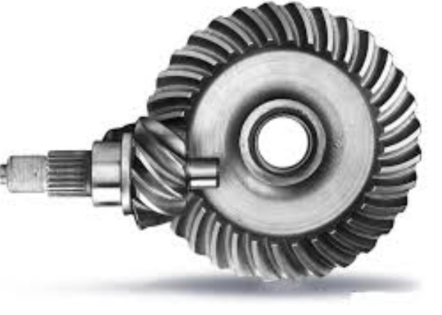
1. Hypoid Gear Parameter Design
The geometric parameters of hypoid gears are calculated based on the Gleason hypoid gear blank calculation formula and the characteristics of larger transmission ratio and spiral angle. The following table summarizes the main design parameters and their calculation methods:
| Parameter | Calculation Method |
|---|---|
| Pitch cone angle of large gear δ’2 | tanδ’2=z2sin∑/1.2(z1+z2cos∑ |
| Initial value of large gear node radius r2 | r2=1/2(de2-b2sinδ’2) |
| Initial value of small gear offset ε’0 | sinε’0=Esinδ’2/r2 |
| Initial value of small gear spiral angle β20 | Assumed value (e.g., 35°) |
| Initial value of magnification factor k’ | k’=1/(cosε’0-tanβ20sinε’0 |
| Initial value of small gear pitch circle radius r’1 | r’1=k’i12r2 |
| Initial value of small gear shaft section offset angle η1 | tanη1=E/[r2(tanδ’2sin∑+cos∑)+r’1] |
After iterative calculation, the final parameters of the hypoid gear are obtained, as shown in the following table:
| Item | Pinion | Gear |
|---|---|---|
| Number of teeth | 2 | 60 |
| Module (mm) | 7.806 | – |
| Midpoint normal module (mm) | 5.961 | – |
| Tooth width (mm) | 88.19 | 47.80 |
| Offset (mm) | 133.84 | – |
| Pressure angle () | 20.00 | – |
| Shaft angle () | – | 90.00 |
| Outer cone distance (mm) | 165.81 | 238.86 |
| Addendum height (mm) | 11.90 | 0.00 |
| Dedendum height (mm) | 2.63 | 14.53 |
| Total tooth height (mm) | 14.53 | 14.53 |
| Outer diameter (mm) | 74.38 | 468.44 |
| Pitch cone angle () | 8.88 | 78.68 |
| Face cone angle () | 8.81 | 78.68 |
| Root cone angle () | 8.81 | 78.68 |
| Distance from pitch cone vertex to intersection point (mm) | -9.58 | 4.99 |
| Distance from face cone vertex to intersection point (mm) | 6.69 | 4.99 |
| Distance from root cone vertex to intersection point (mm) | -13.16 | 1.89 |
2. 3D Modeling and Simulation Design
2.1 3D Modeling
The tooth surface equation of the hypoid gear is derived, and the 3D model is established in SolidWorks.
2.2 Hypoid Gear Meshing Simulation Evaluation
- Mesh Generation: The 3D assembly model of the hypoid gear is meshed, with 72,357 elements and 121,602 nodes.
- Nonlinear Iteration Curve: The convergence performance is verified by the nonlinear iteration curve.
- Contact Stress and Equivalent Stress: The maximum contact stress is 552.94 MPa, and the maximum equivalent stress is 667.59 MPa, both less than the allowable stress.
- Stress Variation Curve: The stress fluctuates within 100 MPa after initial impact and then stabilizes.
2.3 Hypoid Gear Fatigue Simulation Evaluation
- Fatigue Life: The minimum fatigue life is 8,721.8 cycles.
- Fatigue Cumulative Coefficient: The maximum fatigue cumulative damage coefficient is 0.11466 < 1.
- Safety Factor: The fatigue safety factor is 2.1022 > 1.
- Effect of Reverse Torque on Fatigue Life: As the reverse torque increases, the gear damage increases, and the minimum fatigue life decreases.
- Effect of Rotational Speed on Fatigue Life: As the rotational speed increases, the gear damage slightly increases, and the minimum fatigue life slightly decreases.
- Effect of Tooth Root Fillet on Fatigue Life: Using a larger tooth root fillet can increase the minimum fatigue life.
2.4 Hypoid Gear Strength Simulation Evaluation
- Stress Analysis: The first principal stress, third principal stress, and contact stress of the gear are analyzed.
- Effect of Tooth Root Fillet on Stress: Larger tooth root fillet radius reduces stress concentration and increases gear strength.
3. Conclusion
- A calculation method for small gear design parameters from large gear design parameters is derived.
- The 3D model of the hypoid gear is established, and the finite element simulation model is obtained.
- Increasing rotational speed and reverse torque reduces the minimum fatigue life, while using different tooth root fillets can increase the minimum fatigue life.
