
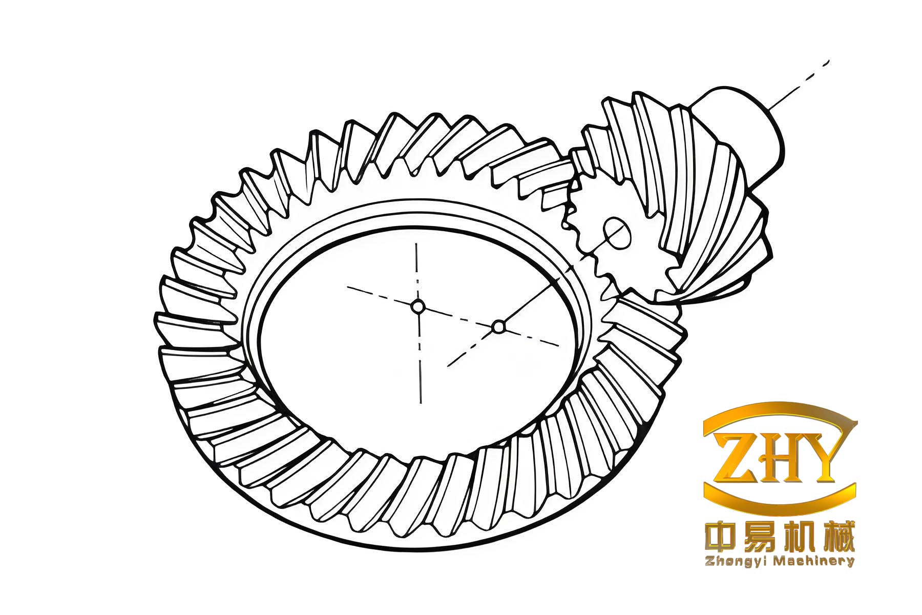
Hypoid gears are a fundamental type of mechanical transmission component used primarily for transmitting motion and power between intersecting or crossing shafts. Because of their offset design, hypoid gears offer greater flexibility in layout and are widely applied in heavy-duty vehicles, precision machine tools, aerospace systems, and marine engineering. The design and machining parameter adjustment of hypoid gears directly determine the meshing performance of the gear pair. Reasonable machining parameters can ensure good tooth contact and low noise. In this paper, I focus on the influence of machining parameter adjustments on the tooth contact analysis (TCA) of hypoid gears, aiming to provide a theoretical basis for practical production.
1. Meshing Theory of Spiral Bevel Gears
The meshing theory of hypoid gears is based on the theory of conjugate surfaces. Unlike ordinary cylindrical gears, hypoid gears transmit motion through point contact in theory, which is realized by the local conjugate principle. The local conjugate principle states that the tooth surfaces of the gear pair are not exactly conjugate; instead, the pinion tooth surface is modified to create a localized contact pattern. The contact under load becomes an ellipse due to elastic deformation.
Let \(S_1\) and \(S_2\) be two moving surfaces. The position vector of a point on surface \(S_1\) in its attached coordinate system \(\sigma_1\) is expressed as
$$ \mathbf{r}_1(u,v,t) = x_1(u,v)\mathbf{i}_1(t) + y_1(u,v)\mathbf{j}_1(t) + z_1(u,v)\mathbf{k}_1(t) . $$
The relative differential formula provides the relationship between absolute and relative differentials:
$$ d\mathbf{r} = d_1\mathbf{r} + \boldsymbol{\omega} \times \mathbf{r} \, dt , $$
where \(\boldsymbol{\omega}\) is the angular velocity of the moving coordinate system. This formula is essential for deriving the meshing equation.
For two tooth surfaces in contact, the position and normal vectors must satisfy
$$ \mathbf{r}_2 = \mathbf{m} + \mathbf{r}_1 , \quad \mathbf{n}_2 = \mathbf{n}_1 , $$
where \(\mathbf{m}\) is the vector connecting the origins of the two coordinate systems. Additionally, the relative velocity at the contact point must be perpendicular to the common normal:
$$ \mathbf{v}_{12} \cdot \mathbf{n} = 0 . $$
This is the fundamental meshing equation.
The induced curvature of two conjugate surfaces is important for local conjugate design. Along the direction \(\mathbf{v}\) in the common tangent plane, the induced normal curvature is
$$ \tilde{k}_v = k_v^{(1)} – k_v^{(2)} = \frac{a v^2}{q_n + a v} , $$
where \(a\), \(q_n\) are auxiliary quantities determined by the relative motion and the surface geometry. Similarly, the induced geodesic torsion is
$$ \tilde{\tau}_g = \frac{a(\mathbf{t} \cdot \mathbf{a})}{q_n + a v} . $$
Applying Euler’s formula, the induced normal curvature in any direction \(\alpha\) is
$$ \tilde{k}_\alpha = \frac{a}{q_n + a v} . $$
These formulas allow the calculation of the contact ellipse dimensions when the tooth surfaces are elastically loaded.
2. Coordinate Transformation and Tooth Surface Equations
To generate the tooth surfaces of hypoid gears, I establish coordinate systems for the gear blank, the cutter, and the machine. The transformation from one coordinate system to another is carried out by homogeneous transformation matrices.
For rotation about the \(x\)-axis by an angle \(\theta\), the transformation matrix is
$$ \mathbf{M} = \begin{bmatrix} 1 & 0 & 0 \\ 0 & \cos\theta & \sin\theta \\ 0 & -\sin\theta & \cos\theta \end{bmatrix} . $$
2.1 Gear Tooth Surface
The gear (wheel) is manufactured by the generating method using a face-mill cutter. The cutter blade traces a conical surface in the cutter coordinate system. The position vector of a point on the cutter cone is
$$ \mathbf{r}_0 = \begin{bmatrix} r_{02} \cos\theta_2 \\ r_{02} \sin\theta_2 \\ 0 \end{bmatrix} , $$
where \(r_{02}\) is the cutter radius and \(\theta_2\) is the phase angle. After transforming to the machine coordinate system, the cutter cone surface is expressed as
$$ \mathbf{r}_2 = \mathbf{r}_0 + s_2 \mathbf{t}_2 , $$
where \(s_2\) is the distance from the blade tip along the generator, and \(\mathbf{t}_2\) is the unit tangent vector of the cutter cone generator.
The meshing equation between the cutter and the gear is derived from the relative velocity condition:
$$ \mathbf{v}_{21}\cdot \mathbf{n}_2 = 0 . $$
Solving for \(s_2\) yields
$$ s_2 = \frac{-\langle \boldsymbol{\omega}_2 \times \mathbf{r}_2, \mathbf{n}_2\rangle}{\langle \boldsymbol{\omega}_2 \times \mathbf{t}_2, \mathbf{n}_2\rangle} . $$
After substituting \(s_2\), the gear tooth surface is obtained. The gear tooth surface point distances to the gear axis are given by
$$ r_2 = |\mathbf{r}_2 \times \mathbf{p}_2| , \quad L_2 = \mathbf{r}_2 \cdot \mathbf{p}_2 , $$
where \(\mathbf{p}_2\) is the unit vector along the gear axis.
2.2 Pinion Tooth Surface
The pinion is machined by the modified roll method (tilted head cutter). The pinion tooth surface is generated by a similar procedure, but the roll ratio is not constant; it is a polynomial function of the cradle rotation angle. I define the pinion coordinate systems and include the modified roll coefficients \(c_2\) and \(d_3\). The pinion rotation angle is expressed as
$$ \varphi_1 = i_{01} \Delta q_1 – c_2 \Delta q_1^2 – d_3 \Delta q_1^3 , $$
where \(\Delta q_1\) is the cradle angle increment. The relative angular velocity and velocity are obtained by differentiating this expression:
$$ \frac{d\varphi_1}{dt} = i_{01} – 2 c_2 \Delta q_1 – 3 d_3 \Delta q_1^2 , $$
$$ \frac{d^2\varphi_1}{dt^2} = -2 c_2 – 6 d_3 \Delta q_1 . $$
The pinion tooth surface is then derived from the meshing condition and the coordinate transformations.
3. Tooth Contact Analysis (TCA)
Tooth contact analysis is a computer-based simulation method to evaluate the contact pattern and transmission error of the hypoid gear pair without actually manufacturing them. I implemented a TCA program in MATLAB based on the equations of both tooth surfaces and the installation conditions.
First, I transform the pinion tooth surface into the gear coordinate system. The installation relationship is shown by the following transformation:
$$ \mathbf{R}_1 = \mathbf{M}_1 \mathbf{r}_1 , \quad \mathbf{R}_2 = \mathbf{M}_2 \mathbf{r}_2 , $$
where \(\mathbf{M}_1\) and \(\mathbf{M}_2\) are rotation matrices about the pinion and gear axes by the roll angles \(\eta_1\) and \(\eta_2\). At a contact point, the position vectors must satisfy
$$ \mathbf{R}_1 – \mathbf{R}_2 = \mathbf{O}_1\mathbf{O}_2 , $$
$$ \mathbf{N}_1 = \mathbf{N}_2 . $$
Because the normal vector equation has three scalar components, the system has six unknowns: \(\Delta q_1, \Delta q_2, \theta_1, \theta_2, \eta_1, \eta_2\). However, \(\eta_1\) and \(\eta_2\) can be solved separately from the normal vector condition. I derived the expressions for \(\eta_1\) and \(\eta_2\) as follows:
$$ \eta_1 = \arcsin\!\left[\frac{\langle \mathbf{p}_2 \times \mathbf{n}_1, \mathbf{p}_1 \times \mathbf{p}_2 \rangle – \langle \mathbf{n}_1, \mathbf{p}_2 \rangle \cos\alpha’}{\langle \mathbf{n}_1, \mathbf{p}_2 \rangle \sin\alpha’}\right] – \alpha’ , $$
where \(\alpha’\) is an auxiliary angle. A similar expression holds for \(\eta_2\).
After eliminating \(\eta_1\) and \(\eta_2\), I solve the remaining three scalar equations:
$$ \mathbf{R}_1(\Delta q_1,\theta_1) – \mathbf{R}_2(\Delta q_2,\theta_2) = \mathbf{O}_1\mathbf{O}_2 . $$
For a given gear cradle angle \(\Delta q_2\), the system can be solved for \(\Delta q_1, \theta_1, \theta_2\). This determines one contact point. By varying \(\Delta q_2\) stepwise, I obtain the entire contact path on the tooth surface.
To make the TCA result more useful, I calculate the so-called V-H adjustments. The V-H adjustment simulates the rolling tester. If the pinion is moved by \(V\) in the vertical direction, \(H\) in the horizontal direction along the pinion axis, and \(J\) along the gear axis, the new offset vector becomes
$$ \mathbf{O}_1\mathbf{O}_2 = \mathbf{O}_1\mathbf{O}_{2,0} + H\mathbf{p}_1 + V\mathbf{j} + J\mathbf{p}_2 . $$
Usually \(J\) is set to zero for the contact point calculation. The values of \(H\) and \(V\) at each contact point are obtained by projecting the position vector difference onto the appropriate directions:
$$ H = -\frac{\langle \mathbf{j} \times \mathbf{p}_2, \mathbf{O}_1\mathbf{O}_2 \rangle}{\sin\Sigma} , \quad V = -\langle \mathbf{j}, \mathbf{O}_1\mathbf{O}_2 \rangle , $$
where \(\Sigma\) is the shaft angle.
The instantaneous transmission ratio is
$$ i(t) = \frac{\langle \mathbf{r}_2, \mathbf{p}_2, \mathbf{n}_2 \rangle}{\langle \mathbf{r}_1, \mathbf{p}_1, \mathbf{n}_1 \rangle} . $$
The transmission error is defined as
$$ \Delta\varepsilon = \varepsilon_2 – \frac{z_1}{z_2} \varepsilon_1 , $$
where \(\varepsilon_1, \varepsilon_2\) are the total rotation angles from the reference position.
3.1 Initial Value Selection
Solving the TCA equations requires good initial guesses. I found that the tangential equation for \(\theta_1\) is almost independent of \(\Delta q_1\) in the domain of interest. By plotting the function using MATLAB’s ezplot, I can determine a suitable initial value for \(\theta_1\). Then, substituting this value, I plot the other equation to obtain the initial value for \(\Delta q_1\). In my study, I chose \(\theta_1 = 0.35\) and \(\Delta q_1 = -0.05\), which converged quickly to \(\theta_1 = 0.3593\) and \(\Delta q_1 = -0.0377\).
4. Gear Blank Three-Dimensional Model
Using the computed tooth surface points, I created the three-dimensional solid models of the hypoid gear and pinion in SolidWorks. The basic blank parameters used in this research are listed in Table 1.
| Parameter | Pinion | Gear |
|---|---|---|
| Number of teeth | 6 | 38 |
| Outer diameter (mm) | 100.24 | 380.6 |
| Mean pressure angle (°) | 22.5 | |
| Pinion offset (mm) | 38 | |
| Shaft angle (°) | 90 | |
| Face width (mm) | 48 | |
| Spiral angle (°) | 50 | 37.09 |
| Pitch angle (°) | 10.92 | 78.81 |
| Face angle (°) | 14.83 | 79.30 |
| Root angle (°) | 10.43 | 74.80 |
| Hand of spiral | Left | Right |
The machine-tool settings for the gear and pinion used in the initial TCA are given in Table 2.
| Processing parameter | Pinion convex | Gear concave |
|---|---|---|
| Cutter radius (mm) | 158.195 | 154.56 |
| Blade angle (°) | -27 | -22.5 |
| Radial position (mm) | 147.7926 | 141.8567 |
| Angular position (°) | 69.12 | 57.15 |
| Machine root angle (°) | 10.43 | 74.80 |
| Vertical offset (mm) | 38.1528 | -2.3472 |
| Sliding base (mm) | -1.2094 | 1.2689 |
| Apex offset (mm) | 3.6316 | -1.9152 |
| Roll ratio | 6.4074 | 1.0027 |
Using the tooth surface equations, I calculated 45 grid points on each tooth surface. Table 3 lists a subset of the gear tooth surface point coordinates in the blank coordinate system.
| X | Y | Z |
|---|---|---|
| 23.448 | -27.6782 | -133.696 |
| 31.1527 | -21.7705 | -140.233 |
| 37.2333 | -13.8804 | -146.769 |
| 41.2277 | -4.4493 | -153.306 |
| 42.7806 | 5.9889 | -159.842 |
| 41.6578 | 16.828 | -166.379 |
| 37.7593 | 27.4097 | -172.915 |
| 31.1299 | 37.047 | -179.451 |
| 21.9694 | 45.0487 | -185.988 |
The three-dimensional models were built by importing these point clouds into SolidWorks and fitting surfaces through them. The gear blank model and the pinion blank model were used for further analysis and visualization.
5. Effects of Machining Parameter Adjustment on Tooth Contact
In hypoid gear manufacturing, small deviations in the machine settings can significantly affect the contact pattern and transmission error. Since the pinion is generally more sensitive to parameter changes, I studied the influence of the pinion machining parameters, including the pitch cone pitch of the generating gear, vertical offset, tooth height curvature correction coefficient, and radial cutter position.
5.1 Effect of Pinion Generating Gear Pitch Cone Pitch
I adjusted the generating gear pitch cone pitch \(R_{01}\) by different amounts. Table 4 lists the values used.
| Case | a | b | c | d | e |
|---|---|---|---|---|---|
| Pitch cone pitch (mm) | 154.2470 | 155.6470 | 155.7470 | 155.8470 | 156.2470 |
The TCA results showed that increasing the pitch cone pitch in the positive direction reduces the internal diagonal contact pattern, while decreasing it intensifies the internal diagonal. The slope of the motion curve at the origin changes as well. When the pitch cone pitch is increased, the contact path moves toward the toe of the pinion; when decreased, it moves toward the heel. The transmission error magnitude is strongly affected by this parameter.
5.2 Effect of Pinion Vertical Offset
The pinion vertical offset \(E_M\) was varied as shown in Table 5.
| Case | a | b | c | d | e |
|---|---|---|---|---|---|
| Vertical offset (mm) | 37.1528 | 37.6528 | 38.1528 | 38.6528 | 38.8528 |
Increasing the vertical offset in the positive direction creates an internal diagonal contact and aggravates the fish-tail pattern. Decreasing the vertical offset reduces the internal diagonal and improves the contact pattern. The motion curve slope at the origin is negative when the vertical offset is too large, meaning the contact path moves toward the tooth root. When the offset is too small, the slope becomes positive and the contact moves toward the tooth top.
5.3 Effect of Tooth Height Curvature Correction Coefficient
The tooth height curvature correction coefficient \(K_P\) was varied according to Table 6.
| Case | a | b | c | d | e |
|---|---|---|---|---|---|
| \(K_P\) | -0.05 | 0 | 0.05 | 0.1 | 0.15 |
Increasing \(K_P\) causes more internal diagonal contact and stronger fish-tail pattern, while decreasing it produces an external diagonal pattern. The influence on the motion curve is similar to that of the vertical offset: positive \(K_P\) shifts the contact to the root, negative \(K_P\) shifts it to the tooth top.
5.4 Effect of Pinion Radial Cutter Position
The radial cutter position \(S_1\) was varied as shown in Table 7.
| Case | a | b | c | d | e |
|---|---|---|---|---|---|
| Radial position (mm) | 147.5926 | 147.6926 | 147.7926 | 147.8926 | 147.9926 |
Increasing the radial cutter position in the positive direction reduces the internal diagonal and moves the contact toward the tooth top. Decreasing the radial position produces an internal diagonal and moves the contact toward the root. The motion curve slope is positive for larger \(S_1\) and negative for smaller \(S_1\).
6. Sensitivity of Machining Parameter Adjustment Errors
In practice, exact settings cannot be achieved on manual or even CNC machines. I introduced small artificial errors to individual processing parameters and analyzed their effect on the TCA results. Table 8 lists the error levels for the gear (large wheel) processing parameters.
| Parameter | a | b | c (nominal) | d | e |
|---|---|---|---|---|---|
| Vertical offset (mm) | -2.3972 | -2.3672 | -2.3472 | -2.3272 | -2.2972 |
| Radial position (mm) | 141.8067 | 141.8367 | 141.8567 | 141.8767 | 141.9067 |
| Angular position (°) | 56.93 | 57.03 | 57.15 | 57.27 | 57.47 |
| Apex offset (mm) | -1.9652 | -1.9352 | -1.9152 | -1.8952 | -1.8652 |
| Sliding base (mm) | 1.2189 | 1.2489 | 1.2689 | 1.2889 | 1.3189 |
For each parameter, I kept all other settings unchanged and performed TCA. The results showed that the gear vertical offset and radial position have a noticeable influence on the motion curve, particularly on its slope at the zero point. For the gear vertical offset, a value larger than nominal produces a negative slope and shifts the contact toward the tooth root; a smaller value produces a positive slope and shifts the contact toward the tooth top. The same trend was observed for the gear radial position. The angular position, apex offset, and sliding base errors had only minor effects on both the contact pattern and the transmission error.
For the pinion, I also introduced similar error levels, as shown in Table 9.
| Parameter | a | b | c (nominal) | d | e |
|---|---|---|---|---|---|
| Vertical offset (mm) | 38.1028 | 38.1328 | 38.1528 | 38.1728 | 38.2028 |
| Radial position (mm) | 147.7426 | 147.7726 | 147.7926 | 147.8126 | 147.8426 |
| Angular position (°) | 68.80 | 69 | 69.12 | 69.24 | 69.44 |
| Apex offset (mm) | 3.5816 | 3.6116 | 3.6316 | 3.6516 | 3.6816 |
| Sliding base (mm) | -1.2594 | -1.2294 | -1.2094 | -1.1894 | -1.1594 |
Among the pinion parameters, the radial cutter position was the most sensitive. The TCA results for the pinion radial position errors are shown in Figure 7 of the original work; here I summarize the key observations. When the pinion radial position is larger than nominal, the motion curve slope is positive and the contact moves toward the tooth top. When it is smaller, the opposite occurs. The pinion vertical offset, angular position, apex offset, and sliding base errors have relatively small effects on the TCA results. However, they may still affect the contact pattern in combination with other errors.
Based on these findings, I conclude that the most sensitive parameters to control in hypoid gear machining are:
- The gear vertical offset
- The gear radial cutter position
- The pinion radial cutter position
These parameters should be set with high precision because they significantly influence the motion curve, which directly relates to transmission smoothness and noise. The other parameters, such as angular position, apex offset, and sliding base, have lower sensitivity and can tolerate slightly larger errors.
7. Practical Guidance for Process Parameter Adjustment
When the TCA result is not satisfactory, I recommend the following adjustment strategy for hypoid gears:
- First adjust the pinion generating gear pitch cone pitch to obtain a reasonably smooth motion curve. This parameter has a strong influence on the transmission error.
- Then adjust the pinion vertical offset or tooth height curvature correction coefficient to control the diagonal contact and fish-tail pattern. These two parameters have similar effects on the contact pattern.
- Finally, fine-tune the pinion radial cutter position to position the contact area correctly in the tooth length direction.
During machine setup, high precision is required for the radial positions of both the gear and pinion, as well as the gear vertical offset. If these parameters deviate from their nominal values by more than the allowed tolerance, the actual contact pattern will differ noticeably from the TCA prediction.
8. Conclusion and Outlook
In this work, I investigated the machining parameter adjustment of hypoid gears based on gear meshing theory and tooth contact analysis. I established the tooth surface equations for both the gear and pinion, implemented a TCA program, and analyzed the influence of several key processing parameters on the contact pattern and transmission error. The main contributions and conclusions are summarized as follows.
First, the mathematical models of the hypoid gear tooth surfaces were built using coordinate transformation and the meshing equation. I solved the tooth surface equations to obtain grid points and created three-dimensional models of the gear blank and pinion blank in SolidWorks.
Second, I developed a reliable TCA program with a practical method for selecting initial values. The program is able to compute the contact path, contact ellipse, and transmission error for a given set of machine-tool settings and installation position.
Third, I studied the effect of adjusting the pinion generating gear pitch cone pitch, vertical offset, tooth height curvature correction coefficient, and radial cutter position. The results indicated that the generating gear pitch cone pitch mainly affects the motion curve shape; the vertical offset and tooth height curvature correction coefficient control the diagonal contact; and the radial cutter position moves the contact pattern along the tooth length direction.
Fourth, I analyzed the sensitivity of the TCA result to machining parameter adjustment errors. The gear vertical offset, gear radial position, and pinion radial position are the most sensitive parameters. They strongly affect the transmission error but have little effect on the contact area. The other parameters are less sensitive and can be set with normal tolerance.
Future work should consider the actual measured tooth surfaces instead of the theoretical ones, as the manufacturing deviations and heat treatment distortions can affect the real contact. Moreover, the combined effect of multiple parameter errors should be studied systematically to provide a complete tolerance specification for hypoid gear machining. I hope this research offers useful theoretical guidance for the design and production of hypoid gears.