
The drive for greater efficiency, power density, and noise reduction in automotive, aerospace, and heavy machinery has positioned hypoid gears as critical power transmission components. Their unique offset-axis configuration allows for smoother engagement and higher torque capacity compared to bevel or spiral bevel gears. However, this advantage comes with immense manufacturing complexity. The intricate, spatially curved tooth surfaces are defined by sophisticated conjugate geometry, making their production a significant challenge that traditionally relies on expensive specialized machines and lengthy trial-and-error setup processes.
This document, crafted from my extensive experience in this field, delves into the transformative role of digital simulation in hypoid gears manufacturing. I will detail the fundamental geometric principles, dissect modern CNC machining strategies, and provide a thorough exposition on building a functional virtual machining environment. This environment enables the precise digital prototyping of the entire cutting process, thereby eliminating physical tryouts, optimizing machine parameters, and generating accurate digital twins for subsequent analysis.
1. Fundamental Concepts and Geometry of Hypoid Gears
Unlike their bevel gear cousins with intersecting axes, hypoid gears feature non-intersecting, offset axes. This offset, typically in the pinion, lowers the drive shaft position in vehicles, contributing to a lower center of gravity. The tooth surfaces are complex hyperboloids of revolution, leading to a combination of rolling and sliding contact that offers superior smoothness and load distribution but demands extreme precision in generation.
The mathematical definition of a hypoid gear tooth surface is rooted in the theory of gearing and the concept of a generating gear. The final tooth flank is the envelope of the tool surface (representing the generating gear tooth) through the prescribed relative motion between the workpiece and the tool. The core geometry is defined by a comprehensive set of machine settings and basic gear parameters.
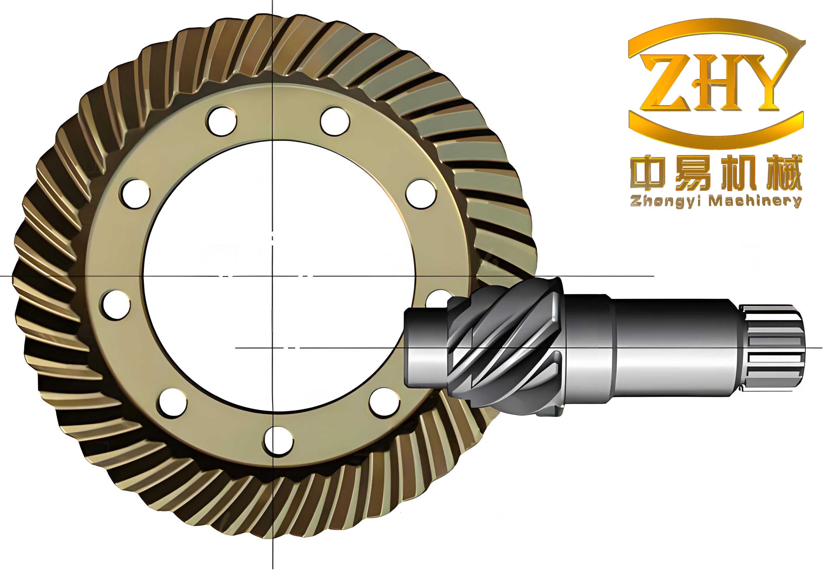
The basic geometric parameters defining a hypoid gear pair include:
| Parameter | Symbol | Description |
|---|---|---|
| Number of Teeth (Pinion/Gear) | $N_p$, $N_g$ | Determines the gear ratio $i = N_g / N_p$. |
| Module / Diametral Pitch | $m_n$ / $P_d$ | Defines the tooth size. |
| Shaft Angle | $\Sigma$ | Typically 90° for automotive applications. |
| Axial Offset | $E$ | The perpendicular distance between the pinion and gear axes. |
| Pitch Angles | $\delta_p$, $\delta_g$ | Angles of the pitch cones ($\delta_p + \delta_g = \Sigma$ for non-hypoid). For hypoid gears, these are derived from the pitch hyperboloids. |
| Face Width | $F$ | Length of the tooth along the pitch cone element. |
| Spiral Angle | $\beta$ | Angle of the tooth trace relative to the pitch cone element, influencing smoothness and strength. |
The tooth surface itself can be represented mathematically as a vector function resulting from the generation process. For a point on the generating tool surface $\mathbf{r}_t(u, \theta)$ (where $u$ and $\theta$ are surface parameters), its position in gear coordinate system after the relative machining motion $\mathbf{M}_{g,t}(t)$ is:
$$ \mathbf{r}_g(u, \theta, t) = \mathbf{M}_{g,t}(t) \cdot \mathbf{r}_t(u, \theta) $$
The generated gear tooth surface is the envelope of this family of surfaces, satisfying the equation of meshing:
$$ \mathbf{n}_t(u, \theta) \cdot \mathbf{v}_t^{(g)}(u, \theta, t) = 0 $$
where $\mathbf{n}_t$ is the unit normal to the tool surface and $\mathbf{v}_t^{(g)}$ is the relative velocity of the tool point with respect to the gear. Solving these equations yields the definitive mathematical model of the hypoid gears tooth flank, which is the foundation for all subsequent simulation and analysis.
2. Manufacturing Processes and CNC Machining Principles
Traditional manufacturing of hypoid gears relied on dedicated mechanical gear generators (e.g., Gleason, Klingelnberg). These machines use complex kinematic chains to realize the relative motion between a crown-gear-shaped cutter and the workpiece. Setting up these machines requires numerous adjustment parameters (machine settings) like root angle, sliding base, swivel, etc., which are non-intuitive and require expert knowledge.
The advent of multi-axis CNC technology revolutionized this field. The fundamental principle—the generating or imaginary crown gear principle—remains the same. A virtual generating gear (the crown gear) is defined mathematically. The cutting tool (a face-mill or face-hob cutter) represents one tooth (or a series of teeth) of this generating gear. The CNC machine’s axes are programmed to synchronously move the workpiece and the tool so that their relative motion precisely mimics the meshing of the workpiece with the imaginary generating gear.
This shift to CNC offers unparalleled flexibility. Different tooth geometries can be produced on the same machine by simply changing the CNC program, without the need for physical change gears or complex mechanical adjustments. The core of the process lies in accurately calculating the tool path, which is defined by the synchronized motion of multiple linear and rotary axes.
A typical 6-axis CNC hypoid gear generator has the following axis configuration:
| Axis | Type | Function in Hypoid Gear Generation |
|---|---|---|
| $X$ | Linear | Radial distance of the cutter center from the workpiece center. Controls the depth of cut and tooth profile. |
| $Y$ | Linear | Provides the axial offset ($E$) between gear and pinion axes. A fundamental setting for hypoid gears. |
| $Z$ | Linear | Controls the initial phase and feed motion along the workpiece axis. |
| $A$ | Rotary (Workpiece) | Rotation of the gear blank. Its angular velocity is synchronized with other axes to create the rolling generating motion. |
| $B$ | Rotary (Tilting) | Orients the workpiece root angle ($\delta$). Critical for setting the correct pitch cone orientation. |
| $C$ | Rotary (Cutter) | Rotation of the cutting tool. For continuous indexing face-hobbing, this is a continuous, synchronized rotation. |
The generating motion for a face-milling process (single-indexing) can be modeled by a set of polynomial functions, where the machine settings are expressed as functions of the generating roll angle $\phi$. For a 5-axis machine (utilizing X, Y, Z, A, B), the motions are often defined as:
$$ X(\phi) = X_0 + X_1\phi + X_2\phi^2 + X_3\phi^3 + X_4\phi^4 $$
$$ Y(\phi) = Y_0 = E \quad \text{(constant for a given gear pair)} $$
$$ Z(\phi) = Z_0 + Z_1\phi + Z_2\phi^2 $$
$$ A(\phi) = \frac{N_g}{N_c} \phi + A_0 \quad \text{(synchronized rotation)} $$
$$ B(\phi) = B_0 \quad \text{(constant root angle)} $$
Here, $N_g$ is the number of gear teeth, $N_c$ is the number of cutter blade groups (for a face-mill), and coefficients $X_i$, $Z_i$ are derived from the basic machine settings and gear geometry to produce the desired tooth flank curvature and longitudinal correction. The simulation system must replicate this coordinated multi-axis motion with high fidelity.
3. Architecture of the Hypoid Gear NC Machining Simulation System
The core objective of the simulation system is to create a digital twin of the physical machining process. This involves constructing precise geometric models of all components and then animating their programmed kinematics to visually simulate material removal. The system I have architected is built on a modular framework, typically developed in an environment like C++ with OpenGL or within a CAD API (e.g., ObjectARX for AutoCAD).
The high-level system architecture comprises the following interconnected modules:
- Data Input Module: Accepts basic hypoid gears design parameters (number of teeth, module, offset, spiral angle, face width, pressure angle) and selects the appropriate cutter head parameters (diameter, blade angle, point radius).
- Geometric Model Generator:
- Workpiece Blank Model: Creates a 3D solid model of the raw forging or stock. For simulation efficiency, this is often a simplified revolution of the basic blank shape (with or without a central bore).
- Cutter Head Model: Generates a 3D solid model of the face-mill cutter. For simulation, the active cutting part can be accurately modeled as a conical or toroidal surface representing the blade edge sweep.
- Machine Tool Model: Constructs a simplified 3D assembly of the CNC machine’s key structural components (bed, columns, slides, spindle heads) using a combination of Constructive Solid Geometry (CSG) and Boundary Representation (B-Rep) techniques for balance between ease of modeling and rendering performance.
- Kinematic & Process Calculator: This is the computational heart. It takes the gear design input and calculates the corresponding machine adjustment parameters (equivalent to traditional machine settings) and, crucially, the time-dependent coordinates for each CNC axis (X, Y, Z, A, B, C) as shown in the polynomial equations above.
- Material Removal Simulation Engine: This module executes the core simulation logic. It discretizes the continuous tool path into small time steps $\Delta t$. At each step, it positions the tool model relative to the workpiece model according to the calculated axis positions and performs a Boolean subtraction operation:
Workpiece_New = Workpiece_Old - (Workpiece_Old ∩ Cutter). The accumulation of these micro-subtractions over the entire tool path yields the final simulated gear tooth geometry. - Visualization & Output Module: Renders the dynamic machining process in real-time and allows user interaction (zoom, pan, rotate). Upon completion, it outputs the precise 3D solid model of the finished hypoid gears, which can be exported for further use.
The process flow within the simulation system is strictly sequential and dependent, ensuring that each stage has the required data from the previous one.
4. Detailed Geometric and Kinematic Modeling for Simulation
4.1 Workpiece and Cutter Solid Modeling
The blank is a revolved solid. Its axial cross-section is defined by parameters like outer diameter, front and back face angles, and bore diameter. A simple 2D profile is created and revolved $360^\circ$ around the workpiece axis. Parametric modeling allows instant generation of different blank sizes.
The face-mill cutter model is more nuanced. A typical cutter comprises a body and inserted blades. For material removal simulation, only the swept volume of the cutting edges is critical. This active volume is modeled as a conical frustum (for straight-sided blades) or a more complex torus-cone blend (for blades with a pointed tip or toprem). The cutter model is also parameterized by diameter, blade angle, tip radius, and number of blade groups.
4.2 Discrete Material Removal via Boolean Operations
Simulating continuous cutting is computationally intensive. The standard approach is discretization. The total generating motion is divided into $N$ intervals. At the $i$-th interval, the tool’s position and orientation $\mathbf{T}_i$ are calculated from the kinematic model. The Boolean subtraction operation is fundamentally:
$$ \mathcal{W}_{i+1} = \mathcal{W}_i \setminus \mathcal{C}(\mathbf{T}_i) $$
where $\mathcal{W}_i$ is the workpiece solid at step $i$, and $\mathcal{C}(\mathbf{T}_i)$ is the cutter solid transformed by $\mathbf{T}_i$. The accuracy of the final simulated gear is directly related to the fineness of the discretization ($N$). A trade-off exists between simulation accuracy and computation time.
4.3 Kinematic Modeling of the CNC Machine
The machine tool is modeled as a kinematic chain. The workpiece coordinate system $\{W\}$ is typically attached to the intersection of its axis and the front face. The cutter coordinate system $\{C\}$ is attached to the cutter center. The transformation from $\{C\}$ to $\{W\}$ is a concatenation of the individual axis transformations. For a machine with axes ordered as Workpiece($A$), Tilt($B$), Linear motions($X, Y, Z$), and Cutter Spindle($C$), the overall transformation matrix is:
$$ \mathbf{M}_{W,C}(t) = \mathbf{Trans}(X(t), Y(t), Z(t)) \cdot \mathbf{Rot}_B(B(t)) \cdot \mathbf{Rot}_A(A(t)) \cdot \mathbf{Rot}_C(C(t)) $$
This matrix $\mathbf{M}_{W,C}(t)$ is precisely what positions the 3D cutter model in the workpiece coordinate system at every simulation time step $t$, enabling the correct Boolean operation. The simulation system essentially acts as a virtual CNC interpreter, executing the motion commands visually and geometrically.
5. Applications of the Simulation Output: TCA and FEA
The primary product of a successful simulation is not just a visualization, but a highly accurate 3D digital model of the machined hypoid gears. This model is a prerequisite for two critical advanced engineering analyses: Tooth Contact Analysis (TCA) and Finite Element Analysis (FEA).
5.1 Tooth Contact Analysis (TCA)
TCA predicts the contact pattern (location, shape, size) and transmission errors under load. It is vital for predicting noise, vibration, and durability. The simulation-generated tooth geometry provides the exact surface data needed. The core of TCA involves solving for the points of contact between the mating pinion and gear tooth surfaces under a prescribed misalignment (e.g., shaft offset error, mounting distance error).
The mathematical condition for contact is that the position vectors and surface normals coincide at the contact point under the assembly position. For pinion surface $\mathbf{r}_p(u_p, \theta_p)$ and gear surface $\mathbf{r}_g(u_g, \theta_g)$, and a misalignment vector $\Delta \mathbf{E}$, the TCA equations are:
$$ \mathbf{r}_p(u_p, \theta_p) = \mathbf{M}(\Delta \mathbf{E}, \phi) \cdot \mathbf{r}_g(u_g, \theta_g) $$
$$ \mathbf{n}_p(u_p, \theta_p) = \mathbf{M}(\Delta \mathbf{E}, \phi) \cdot \mathbf{n}_g(u_g, \theta_g) $$
where $\mathbf{M}$ is the transformation matrix due to misalignment and gear rotation $\phi$, and $\mathbf{n}$ are unit normals. Solving these nonlinear equations yields the transmission error $\Delta \phi$ and the contact path on the tooth surface. The simulation model provides $\mathbf{r}_g$ and $\mathbf{n}_g$ directly from its tessellated or parametric output.
5.2 Finite Element Analysis (FEA)
FEA is used to calculate stress distributions (bending stress, contact stress), root strains, and deflections under operational loads. An accurate 3D solid model is essential for generating a high-quality mesh. The simulation-generated gear model, with its true tooth geometry including fillets and potential modifications, can be directly imported into FEA pre-processors.
A typical workflow involves applying boundary conditions (fixed constraints on the bore), a torque on the pinion shaft, and defining contact pairs between the mating tooth flanks. The maximum contact (Hertzian) stress $\sigma_H$ and root bending stress $\sigma_b$ are key outputs, validated against standards like AGMA or ISO. The table below summarizes the input required from the simulation model for effective TCA and FEA.
| Analysis Type | Primary Input from Simulation | Key Output Parameters |
|---|---|---|
| Tooth Contact Analysis (TCA) | Precise 3D coordinates and normals of the tooth flank surfaces for both pinion and gear. Topology of the tooth surfaces (parametric or point cloud). | Contact pattern (location, size, shape). Transmission Error (TE) function. Sensitivity to misalignments. |
| Finite Element Analysis (FEA) | Watertight 3D solid model of the entire gear body, including accurate tooth geometry, fillets, and web structure. | Root bending stress distribution. Contact stress distribution on the flank. Gear body deflections and load sharing. |
6. Validation, Advantages, and Future Trends
The ultimate validation of any simulation system is its correlation with physical reality. Cutting a physical hypoid gears pair using the exact same CNC program data that drove the simulation provides the benchmark. The validation metrics include:
- Geometric Conformance: Comparing the simulated tooth flank to a coordinate measurement machine (CMM) scan of the physical gear.
- Contact Pattern Match: Comparing the TCA-predicted contact pattern from the simulated gear model with the actual contact pattern obtained from a testing machine under light load.
- Performance Correlation: Assessing if transmission errors and stress predictions from the digital model align with physical dynamometer tests.
The advantages of implementing a robust NC machining simulation system for hypoid gears are substantial and multi-faceted:
| Area of Impact | Benefits |
|---|---|
| Process Development | Eliminates costly and time-consuming physical trial cuts. Allows rapid evaluation and optimization of machine settings and cutter geometry virtually. |
| First-Time-Right Production | Significantly increases the probability of producing a good part on the first physical setup, reducing scrap and machine downtime. |
| Design for Manufacturing (DFM) | Enables early detection of manufacturability issues (e.g., cutter interference, insufficient clearance) while still in the design phase. |
| Digital Thread & Archive | Creates a perfect digital twin of the manufactured part, which serves as a permanent, precise record for quality control, remanufacturing, and future design iterations. |
| Advanced Analysis Enabler | Provides the essential accurate 3D model for reliable TCA and FEA, leading to better, more robust gear designs. |
Looking forward, the integration of simulation systems is moving towards even tighter coupling with the entire product lifecycle management (PLM). Future trends include:
- Physics-Augmented Simulation: Integrating cutting force models, thermal deformation of the workpiece/tool, and machine tool structural dynamics into the geometric simulation to predict surface finish, machining errors, and optimize cutting parameters for efficiency and tool life.
- Closed-Loop Optimization: Using simulation as the forward model within an optimization algorithm that automatically iterates machine settings to achieve a target contact pattern or minimize transmission error, moving towards fully autonomous process planning for hypoid gears.
- Cloud-Based and AI-Enhanced Platforms: Deploying simulation tools on cloud platforms for scalable access and leveraging machine learning to predict optimal setups based on historical data and desired performance outcomes.
In conclusion, the digital simulation of NC machining for hypoid gears represents a paradigm shift from experience-based, trial-and-error manufacturing to a knowledge-based, predictive engineering discipline. By meticulously modeling the geometry and kinematics of the process and leveraging the computational power of Boolean operations and multi-axis interpolation, it is possible to create a virtual proving ground that drastically reduces cost, time, and risk while enhancing quality and enabling deeper engineering insight. As computational power grows and algorithms advance, this virtual realm will become the primary domain for the development and refinement of these indispensable mechanical components.