
Zhang Liang et al. Proposed a calculation method for the position and length of helical gear meshing line. Because this calculation method needs to solve the equations, the driving wheel angle is divided in one meshing cycle of helical gear. The more parts, the lower the solution efficiency, and can not realize rapid calculation.
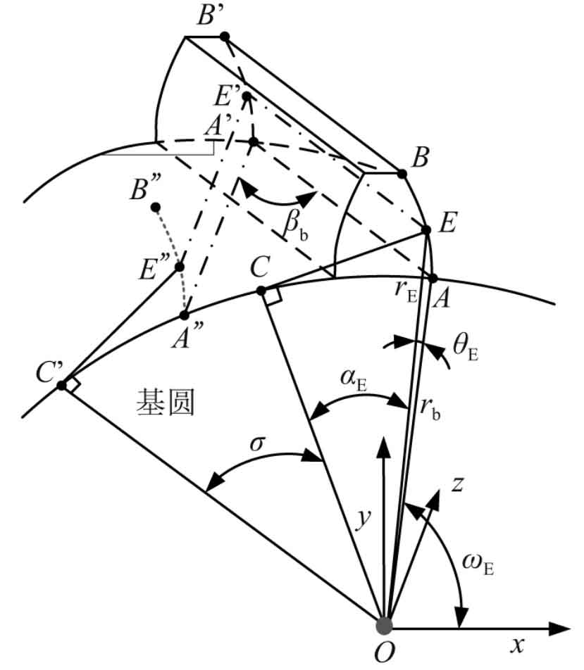
The meshing surface of helical gear is involute spiral surface. According to the meshing principle of spiral surface, the meshing surface of helical gear can be regarded as the spiral movement of involute around Z axis. Based on the left helix, the spatial position expression of helical gear meshing line is derived in this paper. The left helix of involute AB around Z axis reaches involute a’B ‘, as shown in Figure 1.
In figure (1), radius RB is the radius of the base circle of the helical gear, point E is any point on involute AB, and re represents the radial diameter of point E, θ E represents the spread angle of point E, and its pressure angle is expressed by α E indicates. The spatial position expression of point e ‘is:
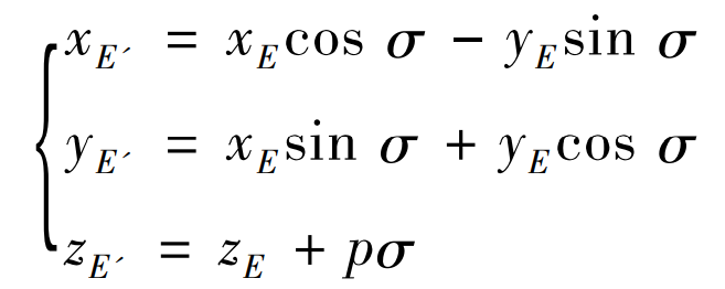
Where: (Xe, ye, Ze) represents the spatial coordinates of any point e of AB on the involute; (Xe ‘, Ye’, Ze ‘) is the coordinate of point e’ on involute a’B ‘; σ Is a parameter variable, which represents the rotation angle of involute AB around Z axis to involute a’B ‘; P is the lead parameter, P = PZ / (2 π), PZ is the lead.
According to the properties of involute, the spatial coordinate expression of any point E on involute AB is:
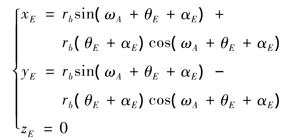
Where: ω A is the angle between OA and axis X. And Tan( α E ) = θ E + α E. Remember Tan( α E) is the meshing position parameter.
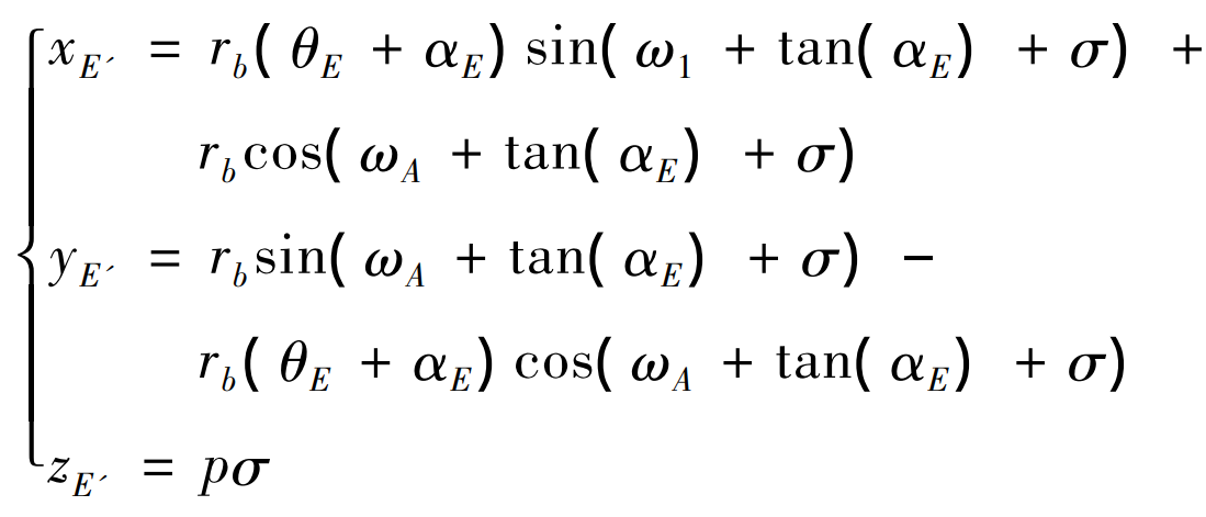
By substituting equation (2) into equation (1), the following can be obtained:
From the end face, the meshing process of helical gear is shown in Figure 2. Suppose the helical gear rotates clockwise, B2 is the starting point of helical gear end face meshing, and B1 is the end point of helical gear end face meshing. N1 and N2 are the tangent points of the common tangent of the meshing gear base circle, p ‘is the meshing gear node, R’1 and R’2 respectively represent the pitch circle radius of the meshing gear, R B1 and R B2 respectively represent the base circle radius of the two meshing gears, and ra1 and ra2 respectively represent the tooth top circle radius of the two meshing gears, α’ T represents the engagement angle of the end face. According to equation (3), the rotation of the meshing gear can be ω A means, in ω B1、 ω B2 represents the rotation position of the starting and ending points B2 and B1 of gear meshing. Equation (4) can be obtained according to the geometric relationship in Figure 2.
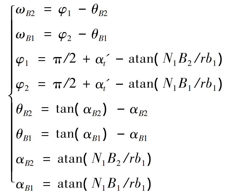
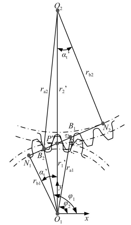
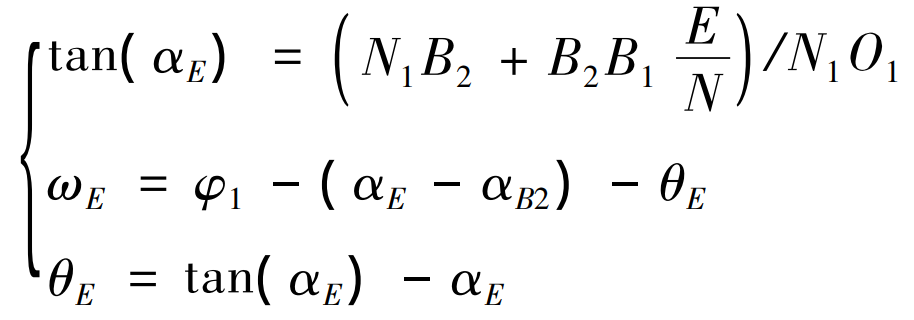
Now b2b1 in Figure 2 is divided into N equal parts, that is, the rotation position [ ω B2, ω B1] and meshing position parameters [Tan]( α B2 ) ,tan( α B1)] is divided into N copies corresponding to one-to-one. Record the rotation position and meshing position parameters of part E ω E,tan( α E)] (where e = 1, 2,…, n-1, n) are:
Simplified:
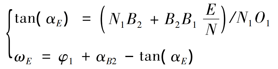
Equation (6) avoids the solution of equations. The [ ω E,tan( α E) By substituting equation (2), the position coordinate value of point K on involute AB on the end face [Xe, ye, 0] can be obtained; As can be seen from equation (3), as long as we know the deflection angle of involute AB around z-axis σ, The spatial coordinate values of point e ‘on involute a’B’ can be obtained [Xe ‘, Ye’, Ze ‘].
According to the meshing characteristics of helical gear, when a driving gear tooth ω B2 go to ω B1, at this time, the gear tooth does not end the meshing state, when the helical gear continues to rotate, that is, when a driving gear tooth from ω B1 go to ω When b1-b / P (where B is the tooth width of the helical gear), the tooth ends meshing. According to the length of tooth width b, from the meshing surface abb’a ‘, the meshing line of helical gear appears in two cases in Fig. 3. When ω B2 - ω When B1 ≤ B / P, one end of the meshing line starts from point a to point B, and the other end of the meshing line is still on point C of AA ‘, as shown in Figure 3 (a). When( ω B2 - ω B1) > b / P, one end of the meshing line starts from point a to point B, and the other end of the meshing line moves from AA ‘to C’ of a’B ‘, as shown in Fig. 3 (b).

The helical gear can be regarded as a sheet helical gear. There is a deflection angle between the adjacent sheet helical gears, which is recorded as Δσ。 The helical gear is divided into m thin helical gears along the tooth width direction AA ‘, and equation (7) can be obtained.
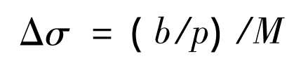
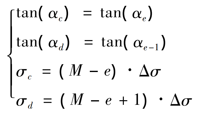
For the convenience of calculation, make Δσ = Δω。 As shown in Fig. 3 (a), when the helical gear pair ω B2 go to ω When B1, the meshing line is BC and BC is divided into M= ω B2 - ω B1 / Δσ Segment, take any segment CD of BC, and note that the meshing position parameters of meshing points c and D are tan respectively( α c ) 、tan( α D) deflection angle values are σ c、 σ d. As shown in equation (8). In equation (8), e represents the position of the meshing point where the meshing point C is projected onto the end face.
In the period from the beginning of meshing in to meshing out of a helical gear pair, the meshing position parameter value and deflection angle value of each meshing point on the meshing line at any rotation position can be determined according to the two boundary conditions of the meshing line in Fig. 3. Substituting equation (8) into equation (3) can obtain the coordinate value of each meshing point of the meshing line. At this time, the length expression of the meshing line is:
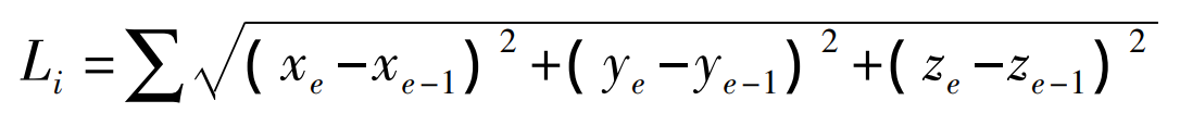
Where: I represents the serial number of rotation position.
According to equation (9), the meshing line length of the helical gear pair at any rotating position can be obtained, so that the total meshing line length in a meshing cycle can be obtained.