
Face gear drives offer compactness, low sensitivity to axial assembly errors, and lightweight configurations. These characteristics make them attractive in aerospace transmissions, where intersecting-axis power transfer must be achieved with high reliability and minimal mass. In a face gear pair, the cylindrical pinion does not carry axial force, which provides a distinct advantage over comparable bevel gear pairs. Nevertheless, the geometric complexity of the face gear tooth surface makes its manufacturing equipment and process chain complicated. This complexity has limited the broad industrial adoption of face gear drives. I have therefore focused my investigation on the precision control and tooth surface formation mechanism of face gear hobbing. The central objective of this work is to establish a systematic modeling and analysis method for improved face gear hobbing, to propose a hob modification strategy that restricts singular points, and to quantify how different machining errors alter the actual face gear tooth surface relative to the theoretical one.
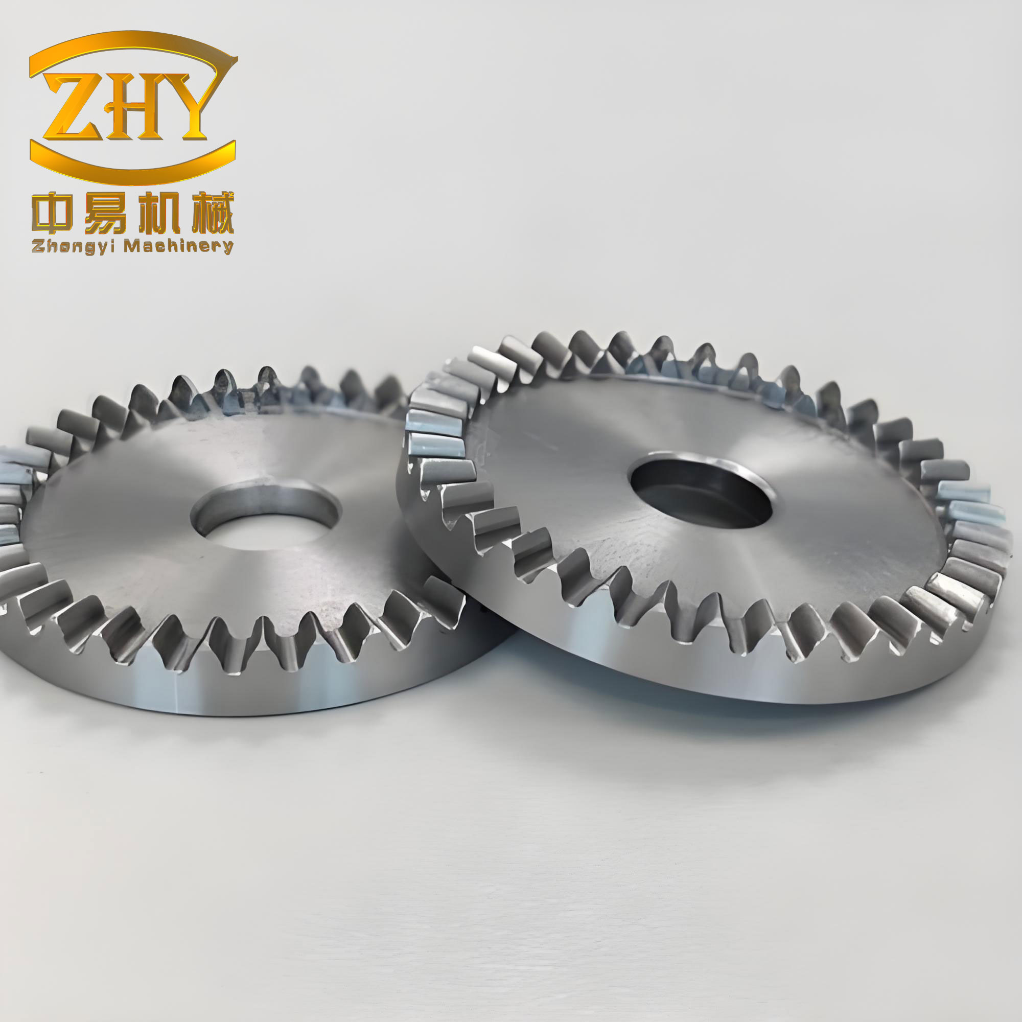
In my approach, the face gear is generated by a six-axis CNC machine tool. The generating process involves the rotation of the hob, the rotation of the face gear blank, and the feed motion of the hob along the radial direction of the face gear. I derive the face gear tooth surface equation and the meshing equations from the forming principle of face gear hobbing and the kinematic characteristics of the six-axis CNC system. I then introduce a hob modification design method that limits the appearance of singular points on the tooth surface and therefore improves machining accuracy. Furthermore, I develop a comparative analysis method between the machined surface and the theoretical surface. This method allows me to study the variation of the face gear tooth profile under different machining error conditions. The results show that the angular error and radial error introduced by the hob have the most significant influence on the tooth surface. These errors should be strictly controlled in actual machining.
1. Introduction
Face gear drives have been studied for several decades. The early mathematical models of face gear drives were established from the theory of gearing. Subsequent researchers investigated the forming theory and contact characteristics of different face gear configurations. For example, eccentric face gear pairs were modeled to study their transmission principle. Modified face gear machining methods based on grinding were proposed, and the contact performance of modified face gears was analyzed. A bidirectional modification tooth surface model for large-scale face gears was constructed, and a spline surface fitted from measured face gear tooth surface coordinates was built. Computer-aided design methods for face gear geometric modeling were also developed to improve the accuracy and efficiency of tooth surface solution.
Early research mainly concentrated on the forming method of face gear machining. The mathematical model and forming machining theory of face gears were established based on the meshing principle of gears, which laid the theoretical foundation for later studies. With the development of CNC technology, the generating method gradually became an important direction for face gear manufacturing. The generating method simulates the generating motion of the gear in space. Because it generates conjugate tooth surfaces based on the gear meshing principle, it has higher theoretical machining accuracy than the forming method.
Hobbing achieves tooth surface generation through the conjugate rolling motion between the tool and the gear blank. It has the advantages of high forming efficiency, good machining flexibility, and the ability to achieve high-precision machining under hard tooth surface conditions. A hobbing coordinate system for non-orthogonal face gears was constructed, and the spatial motion relationship between the tool and the workpiece and the tooth surface formation mechanism were analyzed. An improved hobbing method based on a disk-shaped grinding wheel was proposed, which achieved high-precision modification of the face gear tooth surface. In addition, milling and shaving methods have also been applied to face gear manufacturing. In summary, most studies on face gear pairs have focused on the generation of special-shaped tooth surfaces. Research on the modification machining of face gear tooth surfaces is relatively insufficient. To improve the machining accuracy and error control of face gears, I propose an improved modeling and analysis method for face gear hobbing.
2. Six-Axis CNC Machine Tool Hobbing Model
The tooth surface equation of a face gear can be obtained from its machining motion. The face gear machining process includes the rotary motion of the hob, the rotary motion of the blank, and the feed motion of the hob along the gear radial direction. In the six-axis CNC machine model, the linear axes X, Y, and Z represent the axial, tangential, and radial feed directions, respectively. The rotary axes A, B, and C represent the tool, face gear, and workpiece fixture rotary axes, respectively. The hob and the face gear blank are mounted on the A axis and the B axis, respectively. During machining, the C axis must first be adjusted to the set position. Then the hob is moved to the correct position through the linkage of the Y and Z axes. Finally, the hob is controlled to feed along the X axis.
As shown in the machining principle, there are mainly two motions in the machining process: the feed motion and the rotary motion of the hob. These two motions constitute a two-parameter envelope system. When the hob rotates counterclockwise around the axis \(Z_{so}\) by an angle \(\phi_s\), the face gear blank rotates counterclockwise around the axis \(Z_2\) by an angle \(\phi_2\). According to the relationship shown in the figure, I can establish the following coordinate systems: the coordinate system \(S_s – O_s X_s Y_s Z_s\) rigidly connected to the hob center, the auxiliary coordinate systems \(S_{sr} – O_{sr} X_{sr} Y_{sr} Z_{sr}\), \(S_{so} – O_{so} X_{so} Y_{so} Z_{so}\), \(S_{21} – O_{21} X_{21} Y_{21} Z_{21}\), and \(S_{20} – O_{20} X_{20} Y_{20} Z_{20}\), and the coordinate system \(S_2 – O_2 X_2 Y_2 Z_2\) rigidly connected to the face gear.
2.1 Hob Tooth Surface Equation
According to the face gear machining principle, the generating gear is an involute cylindrical gear. The tooth profile of an involute hob in the axial section is the same as the involute. Therefore, I select an involute hob as the machining tool. The left tooth surface equation \(\mathbf{r}_s\) of the hob base worm and its normal vector \(\mathbf{n}_s\) are expressed as follows:
$$
\mathbf{r}_s(u_s,\theta_s)=
\begin{bmatrix}
r_{bs}[\sin(\theta_s+\theta_{0s}+p u_s)-\theta_s\cos(\theta_s+\theta_{0s}+p u_s)]\\
-r_{bs}[\cos(\theta_s+\theta_{0s}+p u_s)+\theta_s\sin(\theta_s+\theta_{0s}+p u_s)]\\
u_s
\end{bmatrix}
$$
$$
\mathbf{n}_s(u_s,\theta_s)=
\frac{\partial \mathbf{r}_s}{\partial u_s}\times \frac{\partial \mathbf{r}_s}{\partial \theta_s}
=
\begin{bmatrix}
p\sin\theta_s – u_s\sin\alpha\cos\theta_s\\
p\cos\theta_s + u_s\sin\alpha\sin\theta_s\\
u_s\cos\alpha
\end{bmatrix}
$$
Here, \(u_s\) is the tooth direction parameter, \(\theta_s\) is the involute parameter, \(\theta_{0s}\) is the reference angle of the base circle involute, \(p\) is the helical parameter, \(p>0\) denotes a right-handed worm, \(p<0\) denotes a left-handed worm, \(\alpha\) is the pressure angle, and \(r_{bs}\) is the base circle radius of the worm.
Based on the hobbing motion shown in the machining model, the face gear tooth surface equation \(\mathbf{r}_2\) can be expressed as:
$$
\mathbf{r}_2(u_s,\theta_s,\phi_s,\phi_2,l_s) = \mathbf{M}_{s2}^{ss}(\phi_s,\phi_2,l_s) \cdot \mathbf{r}_s(u_s,\theta_s)
$$
where \(l_s\) is the feed motion parameter, \(\phi_s\) is the counterclockwise rotation angle of the hob around the axis \(Z_{so}\), \(\phi_2\) is the counterclockwise rotation angle of the face gear blank around the axis \(Z_2\), and \(\mathbf{M}_{s2}^{ss}\) is the coordinate transformation matrix from the coordinate system \(S_s – O_s X_s Y_s Z_s\) to the coordinate system \(S_{20} – O_{20} X_{20} Y_{20} Z_{20}\).
When studying the hobbing meshing equation, the two motions of the CNC machine tool A axis and X axis should be regarded as independent variables. Therefore, two sets of meshing equations \(f^{(1)}\) and \(f^{(2)}\), as well as the tooth surface equation \(\mathbf{r}_2\), must be satisfied simultaneously. The meshing equations \(f^{(1)}\) and \(f^{(2)}\) can be expressed as:
$$
\begin{cases}
f^{(1)} = \left(\frac{\partial \mathbf{r}_2}{\partial \theta_s}\times \frac{\partial \mathbf{r}_2}{\partial u_s}\right)\cdot \frac{\partial \mathbf{r}_2}{\partial \phi_2} = 0\\
f^{(2)} = \left(\frac{\partial \mathbf{r}_2}{\partial \theta_s}\times \frac{\partial \mathbf{r}_2}{\partial u_s}\right)\cdot \frac{\partial \mathbf{r}_2}{\partial l_s} = 0
\end{cases}
$$
2.2 Hob Modification Design
When machining a face gear on a six-axis CNC machine tool, the hob can be regarded as a helical gear with a large helix angle and a small number of teeth. The hob contacts the end face of the blank during face gear machining, which is different from the contact mode when machining cylindrical gears. Therefore, when the hob base worm performs spatial conjugate motion with the face gear, obvious interference occurs at multiple positions on the inner diameter of the face gear. Further machining verification shows that when a standard involute hob is used to machine a face gear on a six-axis CNC machine tool, the tooth surface is distorted by interference. The tooth tip and tooth root are both deformed, and there is a significant deviation from the theoretical tooth profile.
Whether root cutting occurs can be judged by the velocity of the contact point on the face gear blank. For any contact point \(m\), the velocities \(\mathbf{v}_m^{(2)}\) and \(\mathbf{v}_m^{(s)}\) in the coordinate systems \(S_2\) and \(S_s\) can be expressed as:
$$
\mathbf{v}_m^{(2)} = \mathbf{v}_m^{(s)} + \mathbf{v}_s^{(\phi_s)}\frac{d\phi_s}{dt} + \mathbf{v}_s^{(l_s)}\frac{dl_s}{dt}
$$
$$
\mathbf{v}_m^{(s)} = \frac{\partial \mathbf{r}_s}{\partial u_s}\frac{du_s}{dt} + \frac{\partial \mathbf{r}_s}{\partial \theta_s}\frac{d\theta_s}{dt}
$$
where \(\mathbf{v}_s^{(\phi_s)}\) is the angular velocity component of the velocity at point \(m\), \(\mathbf{v}_s^{(l_s)}\) is the feed velocity component of the velocity at point \(m\), and \(t\) is the machining time.
When the contact point velocity \(\mathbf{v}_m^{(2)} = 0\), a singular point appears on the tooth surface. The velocity \(\mathbf{v}_m^{(2)}\) of point \(m\) in the coordinate system \(S_2\) must satisfy:
$$
\mathbf{v}_m^{(2)} =
\frac{\partial \mathbf{r}_s}{\partial u_s}\frac{du_s}{dt} +
\frac{\partial \mathbf{r}_s}{\partial \theta_s}\frac{d\theta_s}{dt} +
\mathbf{v}_s^{(\phi_s)}\frac{d\phi_s}{dt} +
\mathbf{v}_s^{(l_s)}\frac{dl_s}{dt} = 0
$$
By taking the partial derivatives of the two sets of meshing equations in equation (5) with respect to the four variables \(\theta_s\), \(u_s\), \(\phi_s\), and \(l_s\), I obtain homogeneous linear equation systems with four unknowns and five equations, \(f^{(1)}\) and \(f^{(2)}\), which can be expressed as:
$$
f^{(1)}_{u_s}\frac{du_s}{dt} + f^{(1)}_{\theta_s}\frac{d\theta_s}{dt} + f^{(1)}_{\phi_s}\frac{d\phi_s}{dt} + f^{(1)}_{l_s}\frac{dl_s}{dt} = 0
$$
$$
f^{(2)}_{u_s}\frac{du_s}{dt} + f^{(2)}_{\theta_s}\frac{d\theta_s}{dt} + f^{(2)}_{\phi_s}\frac{d\phi_s}{dt} + f^{(2)}_{l_s}\frac{dl_s}{dt} = 0
$$
Combining the above two equations, I obtain a system containing four unknowns and five related homogeneous equations. Its coefficient matrix \(\mathbf{M}_c\) can be expressed as:
$$
\mathbf{M}_c =
\begin{bmatrix}
\frac{\partial x_s}{\partial u_s} & \frac{\partial x_s}{\partial \theta_s} & v_{x_s}^{(\phi_s)} & v_{x_s}^{(l_s)}\\
\frac{\partial y_s}{\partial u_s} & \frac{\partial y_s}{\partial \theta_s} & v_{y_s}^{(\phi_s)} & v_{y_s}^{(l_s)}\\
\frac{\partial z_s}{\partial u_s} & \frac{\partial z_s}{\partial \theta_s} & v_{z_s}^{(\phi_s)} & v_{z_s}^{(l_s)}\\
f^{(1)}_{u_s} & f^{(1)}_{\theta_s} & f^{(1)}_{\phi_s} & f^{(1)}_{l_s}\\
f^{(2)}_{u_s} & f^{(2)}_{\theta_s} & f^{(2)}_{\phi_s} & f^{(2)}_{l_s}
\end{bmatrix}
=
\begin{bmatrix}
x_1 & x_2 & x_3 & x_4\\
x_5 & x_6 & x_7 & x_8\\
x_9 & x_{10} & x_{11} & x_{12}\\
x_{13} & x_{14} & x_{15} & x_{16}\\
x_{17} & x_{18} & x_{19} & x_{20}
\end{bmatrix}
$$
where \(v_{x_s}^{(\phi_s)}\), \(v_{y_s}^{(\phi_s)}\), \(v_{z_s}^{(\phi_s)}\) and \(v_{x_s}^{(l_s)}\), \(v_{y_s}^{(l_s)}\), \(v_{z_s}^{(l_s)}\) are the components of the velocity vectors \(\mathbf{v}_s^{(\phi_s)}\) and \(\mathbf{v}_s^{(l_s)}\) in the \(x\), \(y\), and \(z\) directions, respectively.
If all five fourth-order determinants are zero, the equation system has a non-zero solution. This condition can be expressed as:
$$
\Delta_1 = [x_1\ x_2\ x_3\ x_4]^T, \quad
\Delta_2 = [x_2\ x_3\ x_4\ x_5]^T, \quad
\Delta_3 = [x_1\ x_3\ x_4\ x_5]^T
$$
$$
\Delta_1^2 + \Delta_2^2 + \Delta_3^2 = 0
$$
This equation can be regarded as the relationship \(f(u_s,\theta_s,\phi_s,\phi_2,l_s)=0\). Combining this relationship with the tooth surface equation determines the position of the tooth surface limit line \(L\) during the hobbing process. The hob can be modified along the limit line \(L\), thereby effectively avoiding the root cutting phenomenon of the standard hob. The limit line \(L\) can be expressed as:
$$
\begin{cases}
\mathbf{r}_s = \mathbf{r}_s(u_s,\theta_s)\\
f(u_s,\theta_s,\phi_s,\phi_2,l_s) = 0
\end{cases}
$$
According to the limit line \(L\), I can carry out the hob modification design. The process is mainly divided into the following steps. First, I derive the hob tooth surface equation and the limit line equation. Second, I calculate the point cloud data of the involute base worm. The point cloud of the limit line \(L\) can also be obtained in a similar way. Third, I import the base worm point cloud into three-dimensional modeling software to construct the hob model. Fourth, I design the unmodified involute hob. Finally, I use the obtained point cloud of the limit line \(L\) as a constraint to modify the hob, thereby forming an improved hob.
3. Tooth Surface Comparison Analysis Model
Because the face gear structure is complex, an accurate discrete modeling method is required. The steps are as follows. First, I input the basic parameters \(M\), \(N_s\), \(N_2\), \(\alpha\), and \(\gamma\), and solve the relevant intermediate parameters. Second, I obtain the tooth direction coordinate \(y_i\) by discretization and determine the relationship between the parameter \(u_s\) in the tooth profile equation and the tool rotation angle \(\theta_s\). Third, according to the tooth tip parameter \(u_{max}\) and the \(y_2\) coordinate, I solve the transition curve coordinates by combining the tooth surface equations. Fourth, I substitute \((y_2, z_2)\) into the tooth surface equation to obtain \(x_2\). To verify the rationality of the tooth surface machined by the modified hob, I can evaluate its consistency with the theoretical tooth profile by comparing it with the ideal tooth surface, and thereby judge the feasibility of the machining method.
In actual face gear machining, machining errors are unavoidable. Therefore, it is necessary to analyze the influence of tool installation errors on the tooth surface. Because the involute hob simulates the conjugate generation motion of a virtual production gear and the face gear, the study of hob machining errors can be replaced by the machining errors of the virtual production gear. When the virtual gear and the face gear blank perform conjugate generation motion, the machining errors are mainly reflected in the following aspects: angular error \(\Delta\alpha\), offset error \(\Delta E\), radial error \(\Delta r\), and displacement error \(\Delta\sigma\). The tooth surface \(\mathbf{r}’_2\) with machining errors introduced is given by:
$$
\mathbf{r}’_2(\Delta E, \Delta r, \Delta\alpha, \Delta\sigma) = \mathbf{M}_{s2}^{ss}(\Delta E, \Delta r, \Delta\alpha, \Delta\sigma)\mathbf{r}_s
$$
where \(\mathbf{M}_{s2}^{ss}\) is the coordinate transformation matrix with machining errors introduced. It can be written as:
$$
\mathbf{M}_{s2}^{ss}(\Delta E, \Delta r, \Delta\alpha, \Delta\sigma) =
\begin{bmatrix}
\cos\Delta\alpha\cos\Delta\sigma & \cos\Delta\alpha\sin\Delta\sigma & \sin\Delta\alpha & 0\\
-\sin\Delta\sigma & \cos\Delta\sigma & 0 & \Delta r\\
-\sin\Delta\alpha\cos\Delta\sigma & -\sin\Delta\alpha\sin\Delta\sigma & \cos\Delta\alpha & \Delta E\\
0 & 0 & 0 & 1
\end{bmatrix}
$$
To verify the rationality of the tooth surface machined by the modified hob, I compare it with the ideal tooth surface to evaluate its consistency with the theoretical tooth profile, thereby judging the feasibility of the machining method. I establish a comparative analysis model. I obtain the tooth surface equations and meshing equations of the modified hob machined surface and the imaginary tooth surface. According to the tooth surface point cloud extraction method, I solve the point cloud data of the hobbing machined tooth surface and the ideal tooth surface. I discretize the two tooth surfaces uniformly in the \(X_2\) direction and the \(Z_2\) direction with an interval length \(\Delta d\), and obtain \(i \times j\) corresponding points. I record their coordinates \([X(i,j), Y(i,j), Z(i,j)]\). I calculate the difference \(\sigma(i,j)\) between the corresponding points of the two tooth surfaces. The difference between the hobbing machined tooth surface and the imaginary machined tooth surface \(\mathbf{r}_2\) can be determined by the following relationship:
$$
\sigma(i,j) = \left| (\mathbf{r}_2 – \mathbf{r}’_2) \cdot \mathbf{n}_2 \right|
$$
where \(\mathbf{n}_2\) is the normal vector of the face gear tooth surface.
4. Numerical Example and Experimental Validation
To validate the proposed model, I perform a numerical example. The calculation parameters are listed in Table 1.
| Parameter | Value |
|---|---|
| Module \(M\) / mm | 3.175 |
| Number of teeth of generating gear \(N_s\) | 28 |
| Number of teeth of face gear \(N_2\) | 160 |
| Number of teeth of cylindrical pinion \(N_1\) | 26 |
| Pressure angle \(\alpha\) / (°) | 27.5 |
| Shaft angle \(\gamma\) / (°) | 90 |
Based on the hob modification method described in Section 2.2, I design and manufacture a hob for modification, and I conduct a hobbing experiment on a CNC machine tool. The experimental process is significantly improved compared with the tooth surface before modification. I calculate the difference between the machined tooth surface and the theoretical tooth surface. The results show that the difference of the machined face gear tooth surface increases with the increase of the hob pressure angle \(\alpha\). The upper and lower limits of the tooth surface difference also increase. In actual machining, a smaller pressure angle should be selected to improve the tooth surface accuracy.
To further investigate the influence of machining errors, I select 10 uniformly distributed discrete points along the face gear tooth direction. According to equations (13) to (15), I examine the influence of angular error \(\Delta\alpha\) and displacement error \(\Delta\sigma\) from 0.02 rad to 0.10 rad, and offset error \(\Delta E\) and radial error \(\Delta r\) from 0.02 mm to 0.10 mm on the tooth surface difference between the machined tooth surface and the ideal tooth surface at the discrete points.
| Error type | Symbol | Range considered | Observed influence on tooth surface difference |
|---|---|---|---|
| Angular error | \(\Delta\alpha\) | 0.02–0.10 rad | Increases rapidly with error magnitude; outer radius is more sensitive |
| Offset error | \(\Delta E\) | 0.02–0.10 mm | Distribution along tooth direction is relatively stable; nearly linear growth |
| Radial error | \(\Delta r\) | 0.02–0.10 mm | Significantly lower than other errors; weak sensitivity |
| Displacement error | \(\Delta\sigma\) | 0.02–0.10 rad | Most significant; maximum difference can reach 0.46 mm at outer radius |
The results show that with the increase of the amplitude of each type of machining error, the tooth surface difference at the discrete points continues to rise. This indicates that machining errors cause the accumulation of the overall tooth surface difference. As the angular error \(\Delta\alpha\) increases, the growth of the tooth surface difference gradually accelerates. The outer diameter position along the tooth direction is more sensitive to the introduction of angular error. For the offset error \(\Delta E\), the resulting tooth surface difference is relatively stable along the tooth direction, and it grows approximately linearly with the increase of the error amplitude. The tooth surface difference caused by the radial error \(\Delta r\) is significantly lower than that caused by other machining errors. This indicates that its sensitivity in the tooth surface forming process is weak, and its influence on the tooth surface error is limited. The influence of the displacement error \(\Delta\sigma\) on the tooth surface difference is the most significant. The highest point of the tooth surface difference is located at the discrete point of the gear outer diameter. The maximum tooth surface difference can reach 0.46 mm. This shows that the displacement error \(\Delta\sigma\) is the main factor affecting the machining accuracy of the face gear. Therefore, special attention should be paid to the influence of the displacement error \(\Delta\sigma\) on the tooth surface during machining.
5. Influence of Pressure Angle and Error Combinations
In my modeling framework, the pressure angle of the hob is not merely a design parameter. It also affects the sensitivity of the face gear tooth surface to machining errors. I have computed the tooth surface difference for three pressure angles: \(25.0^\circ\), \(27.5^\circ\), and \(30.0^\circ\). The results are summarized in Table 3. As the pressure angle increases, both the upper and lower bounds of the tooth surface difference increase. This trend suggests that a smaller pressure angle is preferable when the goal is to minimize the deviation between the machined face gear tooth surface and the theoretical tooth surface. However, I also note that the pressure angle cannot be reduced indefinitely because it influences the contact strength and the load-carrying capacity of the face gear pair. Therefore, the selection of the pressure angle should be a compromise between geometric accuracy and mechanical performance.
| Pressure angle \(\alpha\) / (°) | Lower bound of difference / mm | Upper bound of difference / mm | Recommended use |
|---|---|---|---|
| 25.0 | 0.002 | 0.365 | High-precision finishing |
| 27.5 | 0.002 | 0.438 | General-purpose hobbing |
| 30.0 | 0.002 | 0.584 | Heavy-load applications |
The comparative analysis model also allows me to study the combined effect of multiple errors. In practice, angular error, offset error, radial error, and displacement error do not act independently. They may appear simultaneously due to fixture errors, tool setting errors, and thermal deformation. I therefore define a combined error vector:
$$
\mathbf{e} = [\Delta\alpha, \Delta E, \Delta r, \Delta\sigma]^T
$$
The resulting tooth surface difference at a discrete point \((i,j)\) can be expressed as a function of the combined error vector:
$$
\sigma(i,j) = \left| (\mathbf{r}_2 – \mathbf{r}’_2(\mathbf{e})) \cdot \mathbf{n}_2 \right|
$$
I evaluate the sensitivity of the face gear tooth surface to each error component by computing the partial derivative of the tooth surface difference with respect to each error:
$$
S_{\Delta\alpha} = \frac{\partial \sigma}{\partial \Delta\alpha}, \quad
S_{\Delta E} = \frac{\partial \sigma}{\partial \Delta E}, \quad
S_{\Delta r} = \frac{\partial \sigma}{\partial \Delta r}, \quad
S_{\Delta\sigma} = \frac{\partial \sigma}{\partial \Delta\sigma}
$$
The sensitivity coefficients provide a quantitative ranking of the error sources. In my calculations, the ranking from most sensitive to least sensitive is:
$$
S_{\Delta\sigma} > S_{\Delta\alpha} > S_{\Delta E} > S_{\Delta r}
$$
This ranking confirms that the displacement error \(\Delta\sigma\) and the angular error \(\Delta\alpha\) are the dominant error sources for the face gear hobbing process. The radial error \(\Delta r\) has the weakest influence. These findings are consistent with the discrete-point analysis presented in the previous section.
6. Discussion
The improved modeling method I have presented has several important implications for face gear manufacturing. First, the derivation of the face gear tooth surface equation and the meshing equations from the six-axis CNC hobbing kinematics provides a rigorous mathematical foundation for simulating the hobbing process. The two-parameter envelope system captures the coupled effect of the hob rotation and the hob feed. This is essential for understanding the tooth surface formation mechanism of face gears, because the face gear tooth surface is generated by the conjugate motion of the hob and the blank.
Second, the hob modification design method based on the limit line \(L\) effectively restricts the occurrence of singular points. Standard involute hobs produce interference and root cutting when used to machine face gears on a six-axis CNC machine tool. The interference is caused by the spatial conjugate motion between the hob base worm and the face gear. By identifying the limit line \(L\) and modifying the hob along this line, I can avoid the severe distortion of the tooth tip and tooth root. The modified hob produces a face gear tooth surface that is much closer to the theoretical surface. This improvement is confirmed by the hobbing experiment.
Third, the comparative analysis method between the machined surface and the theoretical surface provides a systematic way to evaluate the geometric accuracy of the face gear. The method discretizes both surfaces in the \(X_2\) and \(Z_2\) directions and computes the normal difference at each corresponding point. This approach is more informative than a simple global deviation metric because it reveals the spatial distribution of the error. For example, the angular error \(\Delta\alpha\) produces a difference that grows toward the outer radius, while the offset error \(\Delta E\) produces a relatively uniform difference along the tooth direction. The displacement error \(\Delta\sigma\) produces the largest difference at the outer diameter. These spatial signatures can be used to diagnose the dominant error source in a machining process.
Fourth, the error analysis shows that the displacement error \(\Delta\sigma\) and the angular error \(\Delta\alpha\) should be strictly controlled during assembly and operation. The maximum tooth surface difference caused by \(\Delta\sigma\) can reach 0.46 mm, which is significant for a face gear with a module of 3.175 mm. In contrast, the radial error \(\Delta r\) has a much weaker effect. This suggests that the radial positioning of the hob is less critical than its angular orientation and axial displacement. The offset error \(\Delta E\) has a moderate effect and should also be controlled, but its influence is more predictable because it grows approximately linearly with the error amplitude.
Fifth, the choice of pressure angle has a direct impact on the tooth surface difference. A smaller pressure angle reduces the upper bound of the difference, but it also affects the contact ratio and the bending strength of the face gear teeth. Therefore, the pressure angle should be selected according to the specific application. For high-precision finishing, a pressure angle of \(25.0^\circ\) may be appropriate. For general-purpose hobbing, \(27.5^\circ\) provides a reasonable balance. For heavy-load applications, \(30.0^\circ\) may be required to ensure sufficient tooth strength, even though the geometric deviation is larger.
7. Conclusions
I have established a six-axis CNC machine tool hobbing model for face gears. I derived the coordinate transformation relationships of the face gear generating motion and obtained the corresponding coordinate transformation matrix. Based on the restriction of the appearance of singular points on the face gear tooth surface, I proposed a hob modification design method. The method identifies the limit line \(L\) and modifies the hob along this line to avoid root cutting and tooth surface distortion.
I also proposed a tooth surface comparison analysis method. I compared the modified hobbing method with the ideal tooth surface. The face gear tooth surface obtained by the hobbing method has high geometric accuracy and forming rationality. By choosing a smaller pressure angle and a reasonable tooth width range, the tooth surface machining accuracy can be effectively improved. In the face gear hobbing process, special attention should be paid to the displacement error \(\Delta\sigma\). The angular error \(\Delta\alpha\) is also important, especially at the outer radius of the face gear. The offset error \(\Delta E\) has a moderate and relatively uniform effect, while the radial error \(\Delta r\) has the weakest influence.
The results of this work provide a foundation for precision control in face gear hobbing. The proposed models can be used to predict the tooth surface deviation caused by different machining errors and to guide the selection of hob modification parameters, pressure angle, and machine tool settings. Future work may extend the method to non-orthogonal face gears, asymmetric face gears, and face gears with complex modifications. The combination of the six-axis CNC hobbing model with the error sensitivity analysis can also be integrated into a digital twin environment for real-time monitoring and compensation of face gear machining processes.
| Equation | Expression | Role |
|---|---|---|
| Hob tooth surface | \(\mathbf{r}_s(u_s,\theta_s)\) | Defines the involute hob base worm surface |
| Hob normal vector | \(\mathbf{n}_s(u_s,\theta_s)\) | Provides the normal direction for meshing and error projection |
| Face gear tooth surface | \(\mathbf{r}_2 = \mathbf{M}_{s2}^{ss}\mathbf{r}_s\) | Transforms the hob surface to the face gear coordinate system |
| Meshing equations | \(f^{(1)}=0, f^{(2)}=0\) | Enforce the conjugate motion condition |
| Singularity condition | \(\mathbf{v}_m^{(2)}=0\) | Identifies the limit line \(L\) for hob modification |
| Limit line | \(\mathbf{r}_s = \mathbf{r}_s(u_s,\theta_s), f=0\) | Defines the constraint for modifying the hob |
| Error transformation | \(\mathbf{M}_{s2}^{ss}(\Delta E, \Delta r, \Delta\alpha, \Delta\sigma)\) | Introduces machining errors into the tooth surface equation |
| Tooth surface difference | \(\sigma(i,j) = |(\mathbf{r}_2 – \mathbf{r}’_2)\cdot \mathbf{n}_2|\) | Quantifies the deviation between machined and theoretical surfaces |
| Priority | Error source | Symbol | Recommended control strategy |
|---|---|---|---|
| 1 | Displacement error | \(\Delta\sigma\) | Strictly control axial displacement; use high-precision fixtures and online compensation |
| 2 | Angular error | \(\Delta\alpha\) | Minimize angular misalignment; verify tool setting before machining |
| 3 | Offset error | \(\Delta E\) | Control offset within moderate tolerance; monitor linear accumulation |
| 4 | Radial error | \(\Delta r\) | Radial positioning is less critical; standard tolerance is acceptable |
In summary, the improved modeling and analysis method for face gear hobbing provides a comprehensive framework for understanding the tooth surface formation mechanism, designing a modified hob, and controlling machining errors. The method is based on rigorous kinematic and geometric derivations, and it is validated by a numerical example and a hobbing experiment. The face gear tooth surface obtained by the proposed method exhibits high geometric accuracy and forming rationality. The error analysis identifies the displacement error \(\Delta\sigma\) and the angular error \(\Delta\alpha\) as the most critical factors affecting the face gear tooth surface. These findings can be used to improve the precision and reliability of face gear manufacturing in aerospace and other high-performance applications.