
The pursuit of higher power density, reduced noise, and increased reliability in power transmission systems, particularly within the automotive and aerospace sectors, has driven significant interest in advanced gear design. Among various solutions, High Contact Ratio (HCR) spur gears, defined as spur gears with a transverse contact ratio greater than 2.0, offer a compelling advantage. Unlike their Low Contact Ratio (LCR, contact ratio < 2) counterparts, HCR spur gears have more than two pairs of teeth in contact simultaneously during operation. This fundamental characteristic leads to a smoother load transfer, reduced dynamic loads, lower transmission error, and consequently, quieter operation and potentially longer service life. The inherent simplicity of spur gears—characterized by straight teeth parallel to the axis—makes them economically favorable and mechanically robust, as they generate no axial thrust forces, simplifying bearing arrangements. Understanding the elastic behavior, specifically the mesh stiffness and the resulting load distribution among the contacting teeth, is paramount for accurately predicting the static and dynamic performance, contact stress, bending stress, and scoring resistance of HCR spur gear drives.
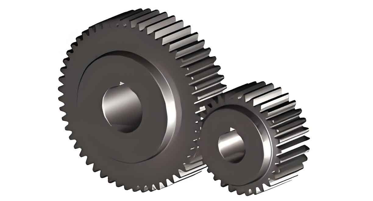
The cornerstone of analyzing gear tooth deflection and load sharing is the accurate calculation of mesh stiffness. International standards such as ISO 6336 and national equivalents provide simplified formulas for gear load capacity, including stiffness and load distribution. However, these methods often rely on approximate empirical coefficients, which can lead to significant inaccuracies, especially for non-standard or high-performance designs like HCR spur gears. Therefore, more precise analytical methods are essential. The energy method, which models the gear tooth as a non-uniform cantilever beam, has proven to be a reliable and efficient approach. This method calculates the total deflection at the load application point by integrating the strain energy due to bending, shear, compressive, and foundation deformations, along with the localized Hertzian contact deformation. The total compliance is the sum of these components, and the stiffness is its inverse.
For a pair of spur gears in mesh, the total deflection \(\delta_{\Sigma}\) under a unit load per unit face width is the sum of individual deflections:
$$\delta_{\Sigma} = \delta_b + \delta_s + \delta_p + \delta_g + \delta_h$$
where \(\delta_b\) is bending deflection, \(\delta_s\) is shear deflection, \(\delta_p\) is compressive deflection, \(\delta_g\) is gear body (foundation) deflection, and \(\delta_h\) is Hertzian contact deflection. The corresponding mesh stiffness \(k\) for a gear pair with face width \(b\) and applied tangential load \(F_t\) is then defined as:
$$k = \frac{F_t / b}{\delta_{\Sigma}}$$
For a single pair of spur gears teeth in contact, this yields the single-tooth-pair stiffness \(k_{single}\). For HCR spur gears, two or three pairs of teeth share the load simultaneously. The total mesh stiffness in these regions, \(k_{mesh}\), is the sum of the stiffnesses of the individual engaging tooth pairs at their specific contact positions along the path of contact.
The load distribution among the contacting teeth in HCR spur gears is governed by the condition of compatibility of deformations. All tooth pairs in contact at any given meshing position must deform by the same amount along the line of action. This principle allows for the calculation of the load shared by each pair. Considering a typical triple-pair contact zone for HCR spur gears, if \(F_t\) is the total transmitted load, and \(F_{AD}\), \(F_{BE}\), and \(F_{CF}\) are the loads on three consecutive tooth pairs (e.g., pairs starting engagement at points A, B, and C), then:
$$F_t = F_{AD} + F_{BE} + F_{CF}$$
The deflection of each pair under its load must be equal: \(\delta_{AD} = \delta_{BE} = \delta_{CF} = \delta\). If \(k_{AD}(s)\), \(k_{BE}(s)\), and \(k_{CF}(s)\) represent the position-dependent single-tooth-pair stiffnesses for each pair, then the load on each pair is \(F_i = k_i(s) \cdot \delta\). The total mesh stiffness is therefore:
$$k_{mesh}(s) = k_{AD}(s) + k_{BE}(s) + k_{CF}(s)$$
and the load share for pair \(i\) is:
$$LSR_i(s) = \frac{F_i}{F_t} = \frac{k_i(s)}{k_{mesh}(s)} \times 100\%$$
The maximum value of \(LSR_i(s)\) over the entire mesh cycle, typically occurring when a tooth pair is near the highest point of single-tooth contact (HPSTC) or during transitions, is the Maximum Load-Sharing Ratio (MLSR). This parameter critically influences the peak bending and contact stresses.
The contact ratio, and consequently the classification as LCR or HCR spur gears, is highly sensitive to basic gear geometry parameters: the addendum coefficient \(h_a^*\), the pressure angle \(\alpha\), the number of teeth \(Z\), and the profile shift coefficient \(x\). To systematically study their effect on stiffness and load sharing, a baseline gear set is defined, and each parameter is varied within ranges that ensure a contact ratio \(\epsilon > 2.0\) for the HCR analysis. The baseline parameters and their variation ranges for HCR conditions are summarized below.
| Parameter | Symbol | Baseline Value | HCR Variation Range (for analysis) |
|---|---|---|---|
| Module | \(m_n\) | 3 mm | Fixed |
| Number of Teeth (Pinion/Gear) | \(Z_1 / Z_2\) | 29 / 100 | Z varied independently |
| Pressure Angle | \(\alpha\) | 20° | 14° to 20° (with adjusted \(h_a^*\)) |
| Addendum Coefficient | \(h_a^*\) | 1.0 | 1.26 to 1.4 |
| Profile Shift Coefficient | \(x_1 / x_2\) | 0 / 0 | -0.5 to 0.11 |
| Face Width | \(b\) | 20 mm | Fixed |
| Young’s Modulus | \(E\) | 206 GPa | Fixed |
| Poisson’s Ratio | \(\nu\) | 0.3 | Fixed |
Using the energy method, the deflection, single-pair stiffness, multi-pair mesh stiffness, and load-sharing ratio are calculated for the pinion across the entire path of contact as these key parameters are varied within their HCR ranges. A nominal unit load of \(F_t/b = 1000\) N/mm is applied for all calculations to isolate geometric effects.
Influence of the Addendum Coefficient \(h_a^*\)
The addendum coefficient directly controls the tooth height. Increasing \(h_a^*\) lengthens the teeth, extending the active profile and generally increasing the contact ratio. For the baseline gear set, an \(h_a^* \geq 1.02\) is required to achieve HCR conditions. Analyzing within the range of 1.26 to 1.4 reveals significant trends. As \(h_a^*\) increases, the tooth becomes more slender near the tip. Under load, this results in notably larger deflections at the tooth tip region compared to changes at the root. The single-tooth-pair stiffness, which reflects the compliance of one idealized pair of spur gears teeth, consequently decreases across the entire mesh cycle. The maximum value of \(k_{single}\) decreases by approximately 9.5% when \(h_a^*\) increases from 1.2 to 1.4.
However, the behavior of the total mesh stiffness \(k_{mesh}\) for HCR spur gears is more complex and more relevant. While transitioning from LCR to HCR causes a substantial increase in the minimum \(k_{mesh}\), within the HCR range itself (from \(h_a^*=1.26\) to 1.4), both the maximum and minimum values of \(k_{mesh}\) decrease. The maximum value decreases by about 6.8%, and the minimum value decreases by about 3.7%. The load distribution becomes more favorable: the maximum load-sharing ratio (MLSR) decreases almost linearly from 60.45% to 57.88% as \(h_a^*\) increases. This means the most heavily loaded tooth pair carries a smaller fraction of the total load, which is beneficial for overall strength.
| Parameter Change (\(h_a^*\): 1.26 → 1.4) | Single-Pair Stiffness \(k_{single}\) | Multi-Pair Mesh Stiffness \(k_{mesh}\) | Maximum Load-Share Ratio (MLSR) |
|---|---|---|---|
| Trend | Decrease | Decrease | Decrease (near linear) |
| Approximate Magnitude of Change | Max: -9.5% (vs. 1.2) Min: -21.2% (vs. 1.2) |
Max: -6.8% Min: -3.7% |
From ~60.45% to ~57.88% |
Influence of the Pressure Angle \(\alpha\)
The pressure angle is a fundamental parameter defining the shape of the involute tooth profile. A higher pressure angle results in a broader tooth base (increasing bending strength) but a stubbier active profile. To achieve HCR conditions with a practical addendum (\(h_a^*=1.3\)), the pressure angle must typically be less than about 21.5°. Within the HCR range of 14° to 20°, increasing \(\alpha\) has a profound effect. The tooth becomes significantly more robust near the root. This leads to reduced deflection at both the initial contact point near the root and the final contact point near the tip for spur gears. The single-tooth-pair stiffness shows a strong increasing trend, with its maximum value rising by approximately 44.1% when \(\alpha\) increases from 14° to 22°.
For the multi-pair mesh stiffness of HCR spur gears, both maximum and minimum values increase substantially within the HCR window. From \(\alpha=14°\) to 20°, \(k_{mesh,max}\) increases by about 22.7% and \(k_{mesh,min}\) by about 24.1%. Contrary to the effect of \(h_a^*\), the load distribution becomes slightly less even as the pressure angle increases. The Maximum Load-Sharing Ratio increases in an almost linear fashion from approximately 53.27% at \(\alpha=14°\) to 61.41% at the HCR limit near \(\alpha=21.45°\). This indicates that while the gears are stiffer overall, the primary load-carrying pair bears a slightly higher portion of the total load.
| Parameter Change (\(\alpha\): 14° → 20° within HCR) | Single-Pair Stiffness \(k_{single}\) | Multi-Pair Mesh Stiffness \(k_{mesh}\) | Maximum Load-Share Ratio (MLSR) |
|---|---|---|---|
| Trend | Increase | Increase | Increase (near linear) |
| Approximate Magnitude of Change | Max: +44.1% (vs. 14° to 22°) Min: +26.3% (vs. 14° to 22°) |
Max: +22.7% Min: +24.1% |
From ~53.27% to ~61.41% (up to 21.45°) |
Influence of the Number of Teeth \(Z\)
Increasing the number of teeth, while keeping the module constant, enlarges the pitch diameter and lengthens the path of contact, directly promoting a higher contact ratio. For spur gears, tooth geometry becomes less curved as Z increases, approximating a rack profile for very high numbers. The analysis considers a wide range from \(Z=29\) to \(Z=300\) (with \(h_a^*=1.3\) to maintain HCR). Deflection decreases slightly at both the root and tip regions as Z increases, primarily due to the larger base circle and changed load angle. The single-tooth-pair stiffness shows a moderate increase, with its maximum value rising by about 8.1% over the full range.
The multi-pair mesh stiffness of these HCR spur gears shows a consistent increase with tooth count. From \(Z=29\) to \(Z=300\), \(k_{mesh,max}\) increases by about 12.1% and \(k_{mesh,min}\) by about 13.7%. The load distribution improves beneficially with more teeth. The Maximum Load-Sharing Ratio decreases, following a trend that resembles an inverse proportional curve, from approximately 59.56% at \(Z=29\) down to about 56.00% at \(Z=300\). This demonstrates that for HCR spur gears, using a higher tooth count (smaller module for a given size) can lead to more favorable load sharing.
| Parameter Change (\(Z\): 29 → 300) | Single-Pair Stiffness \(k_{single}\) | Multi-Pair Mesh Stiffness \(k_{mesh}\) | Maximum Load-Share Ratio (MLSR) |
|---|---|---|---|
| Trend | Increase | Increase | Decrease (inverse-curve) |
| Approximate Magnitude of Change | Max: +8.1% Min: +5.4% |
Max: +12.1% Min: +13.7% |
From ~59.56% to ~56.00% |
Influence of the Profile Shift Coefficient \(x\)
Profile shift is a powerful tool for modifying gear geometry without changing the basic tooth form. For HCR spur gears, negative shift (shifting the tool away from the blank center) is often necessary to avoid undercut and to achieve the desired long addendum for high contact ratio. The analysis varies \(x_1 = x_2\) from -0.5 to 0.2, with HCR conditions valid for \(x < 0.11\) when \(h_a^*=1.3\). As the shift coefficient increases (from negative to positive values), the tooth thickness at the root increases while the tip thickness decreases. This results in reduced deflection at the root and tip. The single-tooth-pair stiffness increases significantly, with its maximum value rising by about 29.2% when x moves from -0.5 to 0.2.
The behavior of the total mesh stiffness for spur gears in the HCR regime is distinct. As x increases from -0.5 towards the positive HCR limit, both the maximum and minimum \(k_{mesh}\) increase. From \(x = -0.5\) to \(x = 0.1\), \(k_{mesh,max}\) increases by about 8.5% and \(k_{mesh,min}\) by about 9.6%. The load-sharing characteristics show a clear trend: the Maximum Load-Sharing Ratio increases almost linearly from a very favorable 52.41% at \(x = -0.5\) to 61.19% at the HCR boundary \(x = 0.11\). This indicates that strong negative profile shift, while still maintaining HCR, can yield exceptionally even load distribution among the contacting teeth in spur gears.
| Parameter Change (\(x\): -0.5 → 0.1 within HCR) | Single-Pair Stiffness \(k_{single}\) | Multi-Pair Mesh Stiffness \(k_{mesh}\) | Maximum Load-Share Ratio (MLSR) |
|---|---|---|---|
| Trend | Increase | Increase | Increase (near linear) |
| Approximate Magnitude of Change | Max: +29.2% (vs. -0.5 to 0.2) Min: +13.8% (vs. -0.5 to 0.2) |
Max: +8.5% Min: +9.6% |
From ~52.41% to ~61.19% (up to x=0.11) |
Comprehensive Summary and Design Implications
The systematic analysis of geometric parameters on the stiffness and load-sharing behavior of High Contact Ratio spur gears reveals complex but predictable interactions. The following table synthesizes the key effects observed within the defined HCR parameter ranges, providing a direct comparison for design guidance.
| Design Parameter | Effect on Single-Pair Stiffness \(k_{single}\) | Effect on Multi-Pair Mesh Stiffness \(k_{mesh}\) (within HCR) | Effect on Maximum Load-Share Ratio (MLSR) | Primary Design Trade-off for HCR Spur Gears |
|---|---|---|---|---|
| Increase Addendum Coeff. \(h_a^*\) | Decreases (tooth becomes more flexible) | Decreases | Decreases (more even sharing) | Improved load sharing vs. reduced overall mesh stiffness and potentially weaker tip. |
| Increase Pressure Angle \(\alpha\) | Increases significantly (broader root) | Increases | Increases (less even sharing) | Higher bending strength and stiffness vs. slightly worsened load distribution and reduced contact ratio window. |
| Increase Number of Teeth \(Z\) | Increases moderately | Increases | Decreases (more even sharing) | Improved load sharing and smoother operation vs. larger pitch diameter or need for smaller module. |
| Increase Profile Shift Coeff. \(x\) (from negative) | Increases significantly | Increases | Increases (less even sharing) | Strong negative shift offers excellent load sharing; moving towards positive increases stiffness but concentrates more load on the main pair. |
In conclusion, the design of High Contact Ratio spur gears involves careful balancing of these geometric parameters to achieve optimal performance. Key findings indicate that:
- Increasing the addendum coefficient (\(h_a^*\)) within the HCR range effectively promotes more even load distribution among the contacting teeth of spur gears, reducing the Maximum Load-Sharing Ratio by nearly 3 percentage points linearly, albeit at the cost of a slight reduction in overall mesh stiffness.
- While a higher pressure angle (\(\alpha\)) substantially increases the single-pair and multi-pair stiffness of spur gears, it leads to a less favorable load distribution, increasing the MLSR linearly by over 8 percentage points across the HCR range. This trade-off must be considered against the need for bending strength.
- Employing a larger number of teeth (\(Z\)) is beneficial for HCR spur gears, as it simultaneously increases mesh stiffness and improves load-sharing evenness, reducing the MLSR according to an inverse-curve relationship.
- Profile shift (\(x\)) is a highly influential parameter. Utilizing significant negative shift is a potent strategy for achieving exceptionally low Maximum Load-Sharing Ratios (below 53%) in HCR spur gears, promoting outstanding load distribution, while subsequent increases toward positive shift raise stiffness but degrade sharing evenness.
This detailed understanding of how stiffness and load-sharing characteristics evolve with basic gear geometry provides a solid analytical foundation for the design, optimization, and strength rating of High Contact Ratio spur gear transmissions, enabling engineers to tailor designs for specific requirements in noise, durability, and power density.