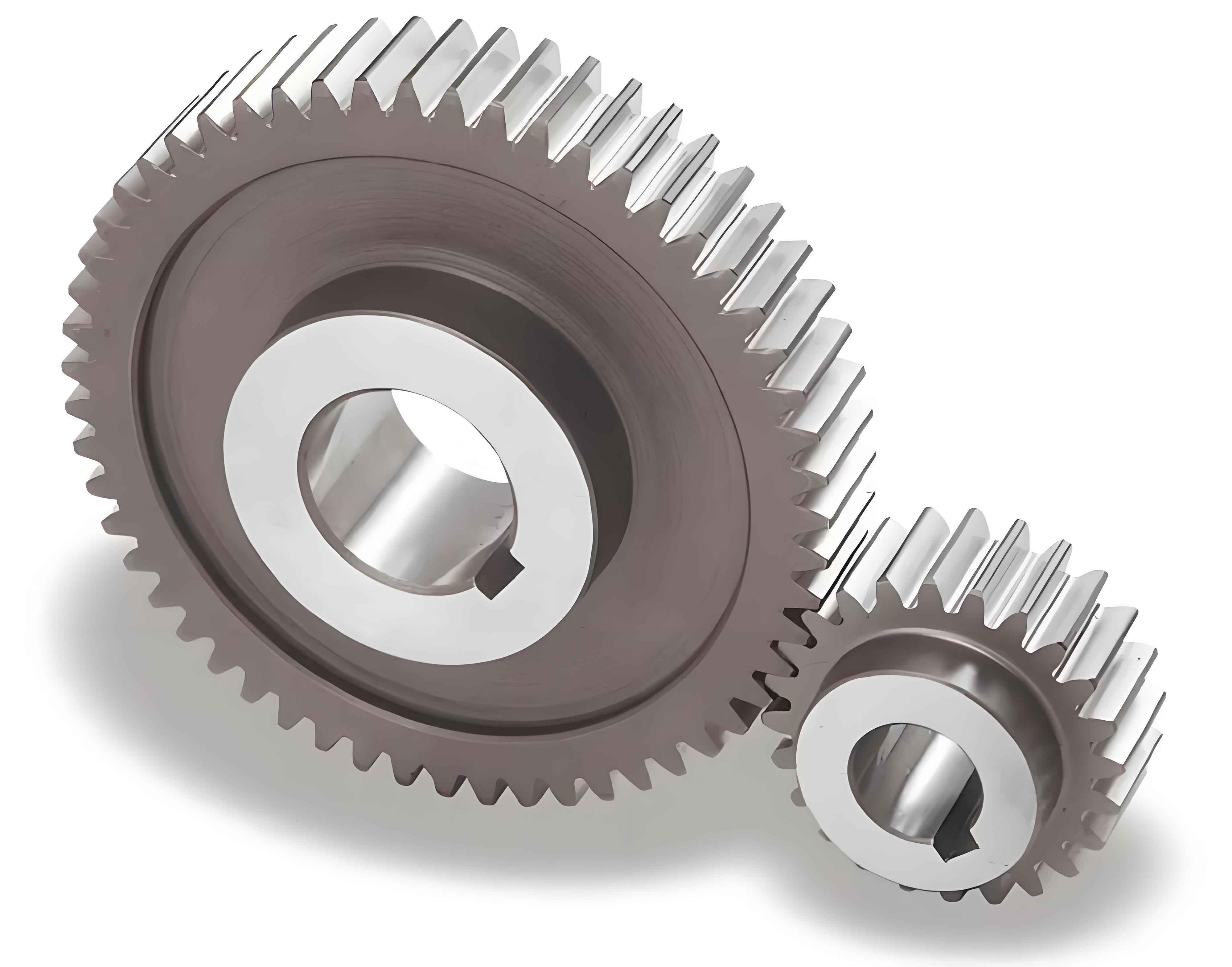
In gear transmission systems, controlling the backlash between meshing gears relies heavily on specifying appropriate tooth thickness tolerances. For spur gears, three critical parameters—constant chord tooth thickness, base tangent length (or Wk), and span measurement (or M-value)—are widely used to quantify tooth thickness variations. This article systematically explores their interrelationships, conversion formulas, and engineering applications.
1. Measurement Methods for Spur Gear Tooth Thickness
1.1 Constant Chord Tooth Thickness
Constant chord tooth thickness (\(S_x\)) is defined as the chordal distance between two symmetrical contact points when a standard rack meshes with the gear. The corresponding height (\(h_x\)) is calculated as:
$$
\begin{aligned}
S_x &= \frac{\pi m}{2} \cos^2 \alpha_f \\
h_x &= h_e – \frac{\pi m}{8} \sin 2\alpha_f – (R_e – R’_e)
\end{aligned}
$$
where \(m\) = module, \(\alpha_f\) = pressure angle, \(h_e\) = addendum height, and \(R_e\), \(R’_e\) = theoretical and measured tip radii. Simplified formulas for common pressure angles are:
| \(\alpha_f\) (°) | Addendum Coefficient | \(S_x\) | \(h_x\) |
|---|---|---|---|
| 20 | 1 | 1.3871m | 0.7476m – (\(R_e – R’_e\)) |
| 15 | 1 | 1.4656m | 0.8037m – (\(R_e – R’_e\)) |
This method suits gears with modules >1 and accuracy grades ≥IT7. However, radial runout and tip diameter errors significantly affect measurement reliability.
1.2 Base Tangent Length (\(W_k\))
Base tangent length represents the distance between two parallel planes tangent to opposite tooth flanks. Its formula for spur gears is:
$$
W_k = m \cos \alpha_f \left[ (k – 0.5)\pi + z \cdot \text{inv} \alpha_f \right]
$$
where \(k\) (number of spanned teeth) = \(0.5 + \frac{z \alpha_f}{180^\circ}\). With typical resolution of 0.05 mm, this method is preferred for precision gears (modules ≥0.5) due to immunity to tip diameter errors.
1.3 Span Measurement (\(M\)-Value)
Span measurement uses precision pins inserted between gear teeth. For even/odd tooth counts:
$$
\begin{aligned}
M &= D_x + d_p \quad (z \text{ even}) \\
M &= D_x \cos \frac{90^\circ}{z} + d_p \quad (z \text{ odd})
\end{aligned}
$$
where \(d_p\) = optimal pin diameter (\(\approx 1.68–1.92m\)). This method offers superior sensitivity (\(\Delta M = 2.75\Delta S_x\) at \(\alpha_f = 20^\circ\)) and is ideal for small-module gears.
2. Increment Relationships Between Parameters
2.1 \(W_k\) vs. \(S_x\)
As shown geometrically:
$$
\Delta W_k = \Delta S_x \cdot \cos \alpha_f
$$
| \(\alpha_f\) (°) | Ratio |
|---|---|
| 20 | 0.940 |
| 15 | 0.966 |
2.2 \(M\)-Value vs. \(W_k\)
For even teeth:
$$
\Delta M = \frac{\Delta W_k}{\sin \alpha_x} \approx \frac{\Delta W_k}{\sin \left(\alpha_f + \frac{90^\circ}{z}\right)}
$$
Odd teeth require correction factor \(\cos \frac{90^\circ}{z}\). Typical ratios:
| \(\alpha_f\) (°) | z=20 | z=90 |
|---|---|---|
| 20 | 2.41 | 2.79 |
2.3 \(M\)-Value vs. \(S_x\)
Combining previous relationships:
$$
\Delta M \approx \Delta S_x \cdot \cot \alpha_f
$$
| Tooth Count | z=20 | z=∞ |
|---|---|---|
| Even | 2.26 | 2.74 |
| Odd (z=19) | 2.24 | – |
3. Practical Applications
3.1 Tolerance Conversion
For a 30-tooth spur gear (\(\alpha_f = 20^\circ\)) with \(S_x\) tolerance −0.020/−0.065 mm:
- \(W_k\) tolerance: −0.019/−0.061 mm (using \(\Delta W_k = 0.94\Delta S_x\))
- \(M\)-value tolerance: −0.050/−0.155 mm (from Table 4)
3.2 Grinding Process Control
When grinding a 25-tooth spur gear (\(\alpha_f = 14.5^\circ\)) with residual \(\Delta M = 31 \mu m\):
$$
\Delta S_x = \frac{\Delta M}{3.86} \approx 8 \mu m
$$
This helps operators adjust grinding depth precisely.
4. Conclusion
The derived relationships between constant chord thickness, base tangent length, and span measurement enable efficient conversions for spur gear design, manufacturing, and inspection. Engineers can utilize the provided tables and formulas to streamline tolerance allocation and process optimization, particularly in high-precision applications where multiple measurement methods are employed.
