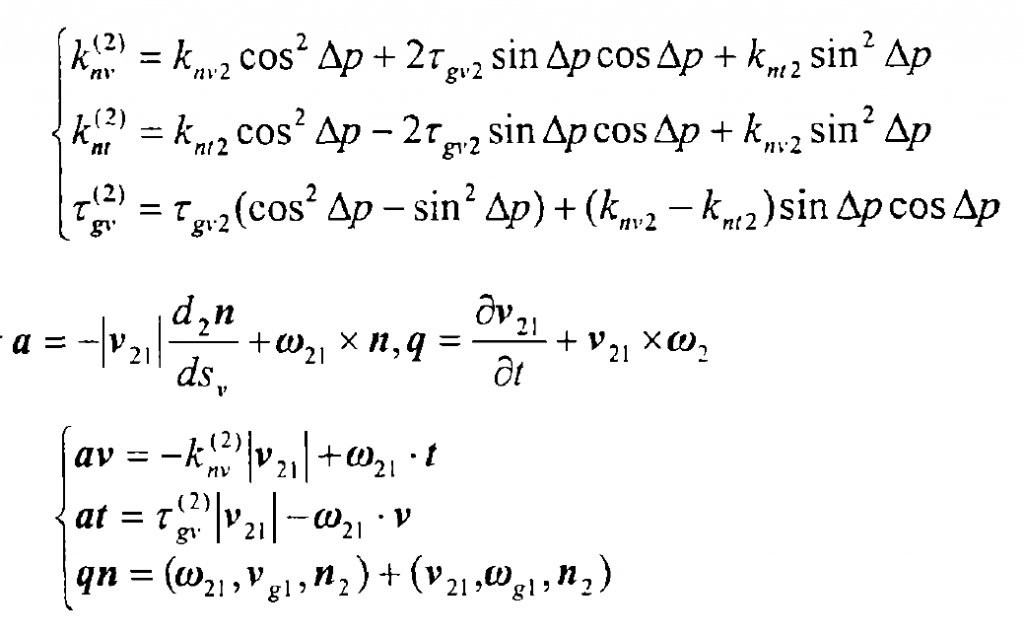
Let the angular velocities of large and small wheels are: ω G2 and ω G1:

The speed of the big wheel and the small wheel at the calculation point M is vg2 and vg1 respectively:

The relative velocities of large and small launches are as follows:

Make the unit vector:

Large and small wheels have the same normal vector N2 at the calculation point M, so that the unit vector t=n2Xv can calculate the curvature of the tooth surface of large and small wheels along the direction v and t, and then modify the tooth surface of the small wheel along the v and t directions.
There is an angle such as Δ p between the direction v and the direction t and the main direction v2 of the large wheel cutter head and the tooth profile direction T2.

The normal curvature and short-range torsion at the calculation point of the tooth surface of the large gear along the direction of vrecoery t are as follows:

Therefore, the induced curvature K _ (21) nt,K _ (21) nv and τ (21) gv of large and small wheels at the calculation point M can be determined by the following formula, where the angle between the ω 12 instantaneous contact line and the direction:

