
In my experience studying and observing the evolution of heat treatment technologies in the railway industry, I have witnessed the profound impact of induction heating on locomotive gear manufacturing. This technology, introduced in China’s locomotive sector during the 1960s, has become a cornerstone for producing gears with hardened layer depths of 2–4 mm and hardness levels of 52–60 HRC. Over four decades, induction-hardened gears have been widely adopted in passenger and freight locomotives (such as DF and SS series) operating below 200 km/h, as well as in urban light rail and subway systems, often replacing imported gear components. However, the journey has been marked by continuous refinement, and the persistent challenge of minimizing heat treatment defects remains at the forefront of technological advancements.
The principle behind induction heating involves using electromagnetic induction to generate eddy currents within the gear material, leading to rapid heating followed by quenching. This process can be described by the fundamental equation for heat generation per unit volume: $$P = \frac{1}{2} \sigma \omega^2 B^2 r^2$$ where \(P\) is the power density, \(\sigma\) is the electrical conductivity, \(\omega\) is the angular frequency, \(B\) is the magnetic flux density, and \(r\) is the radius. This localized heating allows for precise control over the hardened zone, but improper parameters can result in various heat treatment defects, such as incomplete hardening, cracking, or soft spots. In locomotive gears, these defects directly impact fatigue life and operational safety, making their mitigation critical.
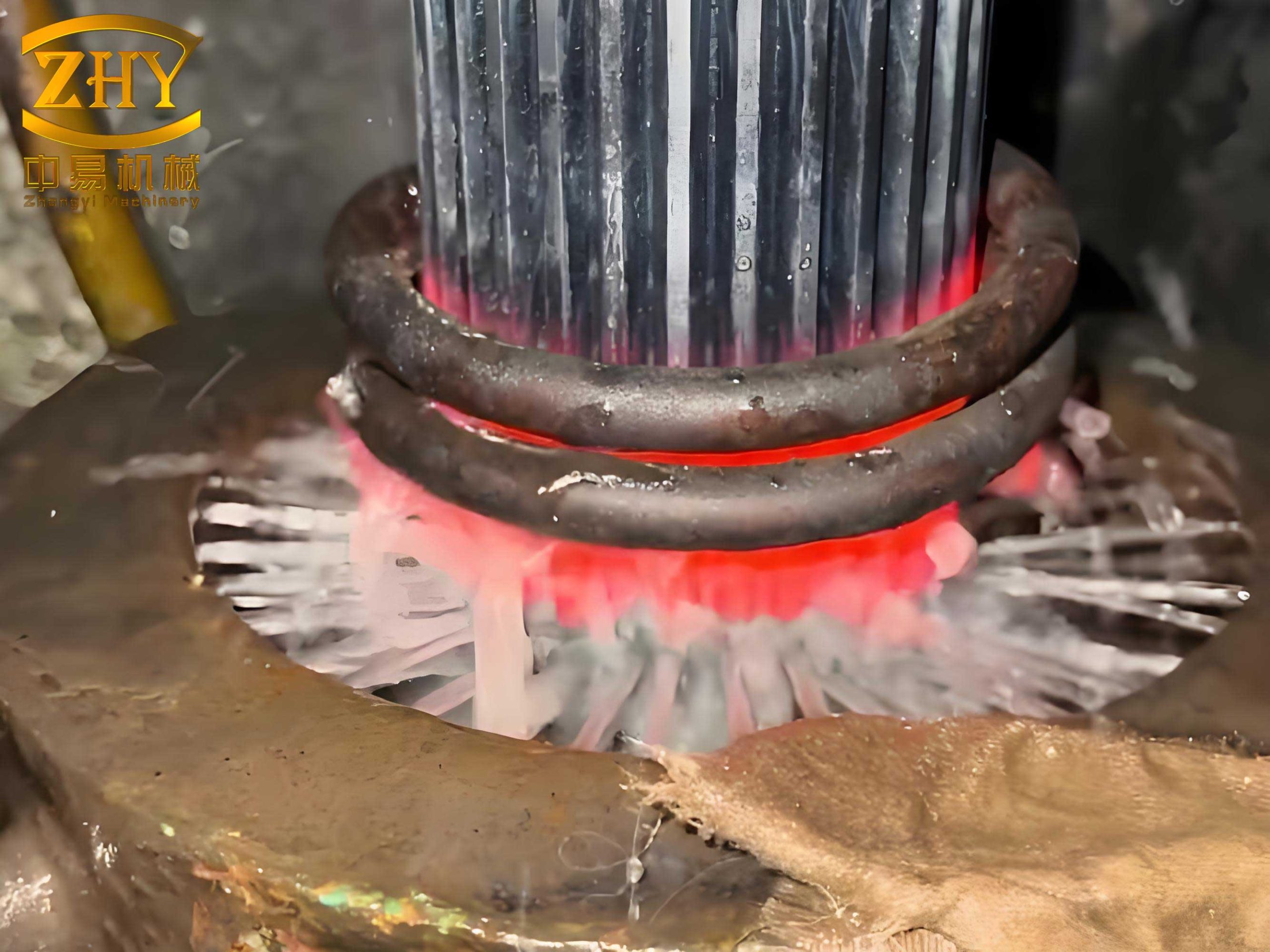
Currently, the state of induction heat treatment for locomotive gears in China relies on medium-frequency oil-submerged contour quenching processes. From the 1970s to the mid-1990s, manufacturers underwent phases of process experimentation, mass production for locomotives below 120 km/h, and localization of imported gears, gradually stabilizing the techniques. Since the mid-1990s, with the rapid expansion of railway networks, operational speeds and hauling capacities have increased, leading to a rise in gear failures during service. Notably, heat treatment defects like non-hardened areas at both ends of the gear tooth width emerged, causing bending fatigue cracks. Through recent research and process adjustments, such as improved quenching methods, full tooth width hardening has been achieved. Consequently, the application speed for induction-hardened gears has escalated from 80–100 km/h to 140–160 km/h, with service life extending from an initial 400,000 km to over 1,000,000 km. Despite these gains, the underlying issues related to heat treatment defects necessitate a deeper examination of current practices.
The equipment landscape reveals significant disparities. Machine tools vary from first-generation hydraulic lift machines with unlimited travel and semi-submerged quenching transformers—a design dating back to the late 1960s—to transitional PLC-controlled hydraulic machines with limit stops, and second-generation screw stepper motor lift, semi-CNC machines. The first-generation machines, still dominant, suffer from poor positioning accuracy and instability, failing to meet modern production demands. Only one second-generation machine, commissioned in 2004, is in use, offering basic compliance but lagging behind contemporary universal quenching machines in technological sophistication. Similarly, power sources predominantly consist of mechanical medium-frequency generators; attempts to adopt domestic thyristor-based medium-frequency power supplies were hindered by reliability issues, and third-generation all-solid-state IGBT medium-frequency power supplies have yet to be implemented in this sector. This equipment stagnation contributes to inconsistent outcomes and exacerbates heat treatment defects.
To elaborate on the technical challenges, I have compiled a table summarizing key aspects of current induction heat treatment practices and associated heat treatment defects:
| Aspect | Current Status | Common Heat Treatment Defects | Impact on Gear Performance |
|---|---|---|---|
| Quenching Process | Medium-frequency oil-submerged contour quenching | Incomplete hardening at tooth ends, uneven hardness distribution | Reduced bending fatigue strength, crack initiation |
| Machine Tool Generation | First-generation (dominant), second-generation (limited) | Poor positioning leading to inconsistent heating, soft spots | Lower durability, increased failure rates |
| Power Source | Mechanical medium-frequency generators | Frequency instability causing overheating or underheating | Microstructural inconsistencies, reduced hardness |
| Cooling Medium | Primarily mineral oil | Inadequate cooling rates, quench cracking | Dimensional distortion, surface cracking |
| Design Theory | Limited to speeds below 160 km/h | Lack of predictive models for defect formation | Uncertainty in high-speed applications |
Beyond equipment, several systemic issues persist. Firstly, theoretical foundations for gears operating above 160 km/h are lacking, creating a void in understanding how induction hardening performs under extreme conditions. This gap often leads to heat treatment defects that only manifest during high-speed service. Secondly, the absence of physical contact and bending fatigue tests on induction-hardened gears means that service life predictions are largely empirical, increasing the risk of undetected defects. Thirdly, stress distribution within the hardened layer remains poorly studied, which is crucial for assessing fatigue resistance and identifying potential heat treatment defects like residual stress concentrations. The stress profile can be modeled using equations like: $$\sigma(x) = \sigma_0 + \frac{E \alpha \Delta T}{1-\nu} \left(1 – e^{-\beta x}\right)$$ where \(\sigma(x)\) is the stress at depth \(x\), \(\sigma_0\) is the surface stress, \(E\) is Young’s modulus, \(\alpha\) is the thermal expansion coefficient, \(\Delta T\) is the temperature gradient, \(\nu\) is Poisson’s ratio, and \(\beta\) is a decay constant. Without such analyses, heat treatment defects related to stress imbalances may go unnoticed.
Furthermore, dual-frequency quenching for gears with modules below 6 mm—used in metro and light rail applications—represents an emerging trend, but it remains at the调研 stage. Designers lack clarity on its applicability and longevity, and no bench tests have been conducted to validate dual-frequency quenched gears. This hesitation stems from fears of introducing new heat treatment defects, such as intergranular oxidation or excessive grain growth, due to improper frequency combinations. The heat transfer during dual-frequency quenching can be expressed as: $$\frac{\partial T}{\partial t} = \kappa \nabla^2 T + \frac{Q}{\rho c_p}$$ where \(T\) is temperature, \(t\) is time, \(\kappa\) is thermal diffusivity, \(Q\) is the heat source from induction, \(\rho\) is density, and \(c_p\) is specific heat. Optimizing this requires precise control to avoid defects.
Additionally, the widespread use of aged quenching machines without CNC controls, servo motor precision, or online real-time monitoring hampers quality consistency. Many domestic equipment manufacturers still produce machines based on decade-old technologies, perpetuating heat treatment defects. The reliance on mechanical medium-frequency generators, rather than modern IGBT sources, adds to energy inefficiency and process variability. Equally concerning is the neglect of cooling media; most manufacturers continue to use oil as the primary quenchant, despite its limitations in achieving ideal hardness profiles. This often results in heat treatment defects like low surface hardness or excessive residual stresses. A comparative analysis of quenchants is essential, as shown in the table below:
| Quenching Medium | Cooling Rate (℃/s) | Typical Hardness Achieved (HRC) | Associated Heat Treatment Defects |
|---|---|---|---|
| Mineral Oil | 50–100 | 52–58 | Soft spots, distortion, smoke emission |
| Polymer Solutions | 70–150 | 54–60 | Inconsistent cooling if concentration varies |
| High-Pressure Gas | 30–80 | 50–56 | Insufficient hardening for deep layers |
| Water | 200–500 | ≥60 | Cracking, severe distortion |
Another overlooked aspect is the coordination between cold and hot processing. Issues such as chamfer size and shape, root roughness, and root arc geometry from machining can adversely affect induction heating and final quality, leading to heat treatment defects like edge cracking or non-uniform hardening. For instance, a sharp corner can cause overheating due to the edge effect, described by: $$Q_{\text{edge}} \propto \frac{1}{\sqrt{r}}$$ where \(r\) is the radius of curvature. Therefore, proper machining tolerances are vital to mitigate defects.
Looking ahead, I believe several directions can enhance the induction heat treatment of locomotive gears and reduce heat treatment defects. First, upgrading to high-precision, automated quenching equipment with CNC controls and servo-driven mechanisms will improve production quality and efficiency. Such machines can monitor parameters in real-time, adjusting for variables that cause defects. Second, dual-frequency quenching equipment should be推广 while validating its effectiveness for metro and light rail gears through rigorous testing. This includes fatigue tests to quantify life expectancy and identify any nascent heat treatment defects. Third, industry associations could spearhead projects to fund basic research on induction-hardened gears, such as mapping stress distributions and determining fatigue strengths. This research can inform standards that minimize defects.
Moreover, adopting advanced power sources like all-solid-state IGBT medium-frequency units can offer better frequency stability and energy efficiency, reducing heat treatment defects linked to power fluctuations. The transition might involve cost-benefit analyses, as summarized in the formula: $$C_{\text{total}} = C_{\text{equipment}} + \sum_{i=1}^{n} (C_{\text{defect}, i} \times P_{\text{defect}, i})$$ where \(C_{\text{total}}\) is the total cost, \(C_{\text{equipment}}\) is the equipment investment, \(C_{\text{defect}, i}\) is the cost of each defect type, and \(P_{\text{defect}, i}\) is its probability. By lowering \(P_{\text{defect}, i}\) through better technology, overall costs decrease.
In terms of cooling, exploring alternative quenchants like polymer solutions or controlled gas quenching could yield more uniform hardness and fewer heat treatment defects. For example, polymers allow adjustable cooling rates by varying concentration, which can be optimized using the Grossmann quench severity factor \(H\): $$H = \frac{k}{2\sqrt{\pi \alpha t}}$$ where \(k\) is the heat transfer coefficient, \(\alpha\) is thermal diffusivity, and \(t\) is time. Higher \(H\) values indicate faster cooling, but must be balanced to avoid cracking. Implementing in-line monitoring of quenchant temperature and contamination can further curb defects.
Lastly, fostering collaboration between machining and heat treatment teams is essential. Establishing guidelines for gear geometry pre-quenching can prevent many heat treatment defects. For instance, specifying root radii above a threshold \(R_{\text{min}}\) ensures even heating: $$R_{\text{min}} = \frac{\delta}{2}$$ where \(\delta\) is the skin depth of induction, given by $$\delta = \sqrt{\frac{2\rho}{\omega \mu}}$$ with \(\rho\) as resistivity and \(\mu\) as permeability. Such interdisciplinary approaches can significantly enhance product reliability.
In conclusion, while induction heat treatment has propelled locomotive gear performance for decades, addressing its shortcomings requires a holistic focus on technology, equipment, and process control. By prioritizing research, modernization, and defect prevention, the industry can achieve gears that meet higher speed demands with minimal heat treatment defects. The journey ahead involves not just incremental improvements but a concerted effort to integrate scientific insights with practical engineering, ensuring that every gear produced withstands the rigors of modern rail transport. Through continuous innovation and vigilance against heat treatment defects, the future of induction-hardened gears looks promising, with potential applications extending beyond current speed limits and into next-generation locomotives.