
In modern manufacturing, gear hobbing stands as a highly efficient method for rough or semi-finishing gear production, offering superior productivity compared to alternatives like gear shaping. Consequently, gear hobbing machines account for approximately 45% to 50% of market share in gear manufacturing. However, many enterprises still rely heavily on empirical knowledge or machining handbooks to select process parameters, often neglecting critical factors such as machine tool vibration, which can significantly degrade machining accuracy. Additionally, assessing gear machining errors typically requires manual measurements using gear measuring centers, leading to reduced production efficiency and accelerated equipment wear. Thus, there is a pressing need for methods that enable rational parameter selection and accurate prediction of gear machining precision. This study investigates the influence of process parameters and vibration signals on tooth profile deviation in high-speed dry gear hobbing and establishes a prediction model to guide parameter optimization.
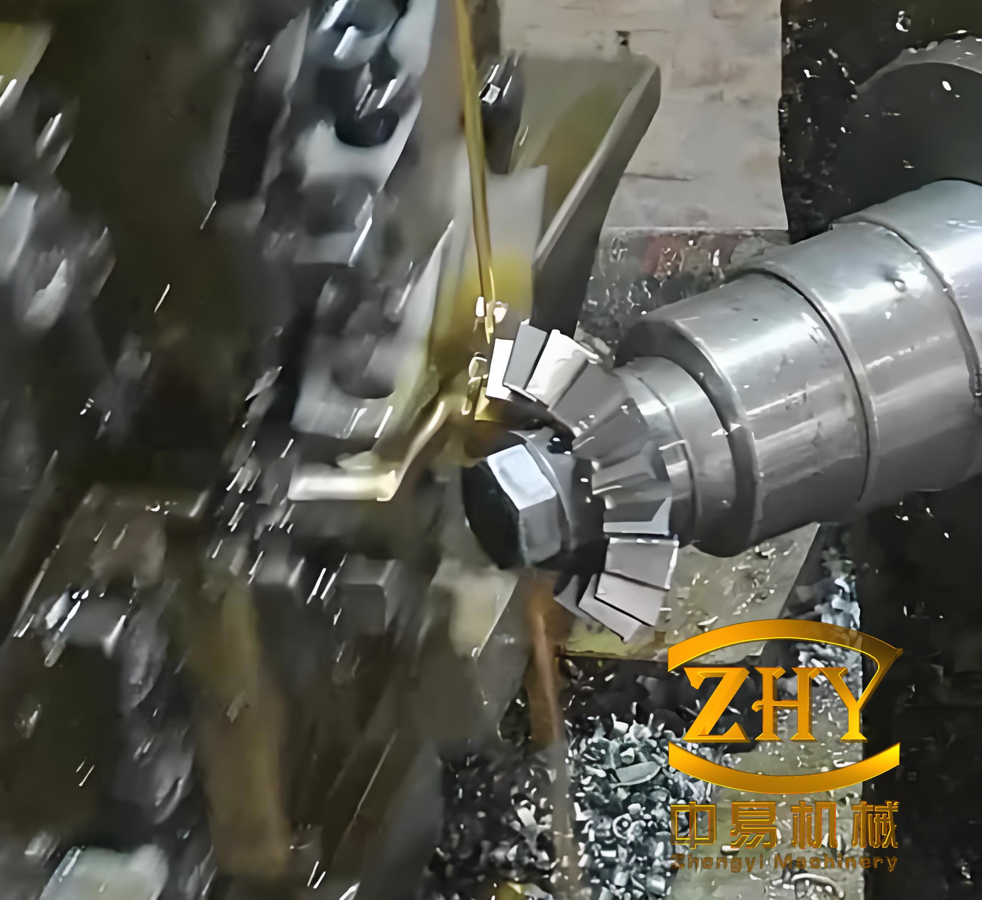
Gear hobbing operates on the principle of worm and worm wheel meshing. The hob, analogous to a worm, features cutting edges formed through grooving and relief grinding. During the gear hobbing process, the hob and workpiece rotate at a specific speed ratio to generate the tooth profile, while the hob moves axially across the workpiece’s full face width. According to the generating principle, the gear tooth profile is enveloped by the trajectory of the cutting edges. Theoretically, by adjusting the meshing speed ratio to maintain the conjugate relationship between the hob and gear blank, gears with the same module but different numbers of teeth can be machined. A key distinction of gear hobbing from turning or milling is its intermittent cutting nature. Unlike gear pair transmission, where single and double tooth meshing alternate, the hob and workpiece exhibit high contact ratio, with contact state changes primarily arising from discontinuous impacts of hob teeth on the workpiece. For instance, in cylindrical helical gear machining, the hob cuts from the workpiece’s upper end, and as it feeds downward, chips of varying volumes are successively removed.
Vibration during gear hobbing arises from two main sources. First, inherent vibrations due to the machine’s operational mode are unavoidable. Second, external factors, such as environmental influences, can induce vibrations that may be mitigated through appropriate measures. Specifically, the latter category stems from interactions between the tool and workpiece. In practical gear hobbing, chip formation leads to hob wear and reduced uncut material volume, causing deformations under force that result in unstable cutting, tooth profile deviations, collisions, and consequent vibration and noise. The gear hobbing system can be simplified as a spring-mass-damper vibration model. For the dynamic gear hobbing process, the governing equations are expressed as:
$$
m\ddot{x}(t) + c_x \dot{x}(t) + k_x x(t) = F_x(t)
$$
$$
m\ddot{y}(t) + c_y \dot{y}(t) + k_y y(t) = F_y(t)
$$
$$
m\ddot{z}(t) + c_z \dot{z}(t) + k_z z(t) = F_z(t)
$$
Here, variables \(x\), \(y\), and \(z\) denote vibration displacements in the X, Y, and Z directions, respectively; \(m\) represents the workpiece mass; \(c_i\) and \(k_i\) (where \(i = x, y, z\)) are the damping and stiffness coefficients in each direction; and \(F_i(t)\) denotes the cutting forces. Variations in chip thickness generate dynamic cutting forces, inducing workpiece vibration and positional deviations that compromise gear geometric accuracy.
To explore the effects of process parameters and vibration on tooth profile deviation, an experimental platform was established using a YK3120CNC gear hobbing machine. Two IEPE piezoelectric triaxial acceleration sensors were mounted on the hob spindle and worktable to capture vibration signals. The sensors were adjusted for optimal orientation in the Y and Z axes. Acceleration data were recorded in real-time via a DH5922D dynamic signal testing system at a sampling frequency of 10,000 Hz. The gear hobbing parameters for the tool and workpiece are summarized in Table 1.
| Category | Parameter | Value |
|---|---|---|
| Gear | Module (mm) | 1.4 |
| Helix Angle (°) | 23.89 | |
| Pressure Angle (°) | 17.1 | |
| Number of Teeth | 22 | |
| Face Width (mm) | 45 | |
| Hob | Module (mm) | 1.4 |
| Thread Lead Angle (°) | 2.33 | |
| Number of Starts | 2 | |
| Number of Flutes | 15 | |
| Outer Diameter (mm) | 70 |
Each set of vibration data contained hundreds of thousands of sampling points. Analysis revealed that samples from 210,000 to 220,000 corresponded to the stable cutting phase, accurately representing the gear hobbing machine’s behavior, and were thus selected as the original dataset. Due to environmental noise, signals required denoising to enhance the signal-to-noise ratio. A wavelet threshold denoising method was applied, utilizing the sym5 wavelet base for two-level decomposition, a minimax principle-based soft threshold function for component filtering, and signal reconstruction to obtain cleaned signals. The Z-axis vibration signals from the hob spindle were prioritized, as they exhibited higher amplitudes and greater sensitivity to machining state changes compared to other directions. For example, denoising effectively reduced high-frequency noise, as evidenced by time-domain and frequency-domain comparisons of raw and processed signals.
An orthogonal experiment was designed to investigate vibration characteristics and their impact on machining accuracy under various conditions. Using identical tools and materials, spindle speed and feed rate were selected as factors, with other parameters held constant. Based on process specifications, spindle speed ranged from 800 to 1600 rpm in increments of 200 rpm, and feed rate varied from 0.7 to 1.5 mm/rev in steps of 0.2 mm/rev. The orthogonal experimental parameters are detailed in Table 2.
| Level | Factor: Spindle Speed \(n\) (rpm) | Factor: Feed Rate \(f\) (mm/rev) |
|---|---|---|
| 1 | 800 | 0.7 |
| 2 | 1000 | 0.9 |
| 3 | 1200 | 1.1 |
| 4 | 1400 | 1.3 |
| 5 | 1600 | 1.5 |
Tooth profile deviation, a key indicator of gear hobbing quality, was measured under constant feed rates while varying spindle speeds. The relationship between tooth profile deviation and spindle speed under five feed conditions is illustrated in Figure 1a. At 800 rpm, deviations were relatively low; increasing speeds generally raised deviations non-linearly, indicating intensified tool wear and spindle vibration. Similarly, the effect of feed rate on tooth profile deviation at different spindle speeds is shown in Figure 1b. At 0.9 mm/rev, workpiece quality improved, but further increases in feed rate elevated deviations due to heightened cutting forces and instability.
Range analysis was employed to assess factor significance, with larger ranges indicating greater influence. As shown in Table 3, spindle speed had the most significant impact on tooth profile deviation, followed by feed rate, and their interaction had the least effect.
| No. | Spindle Speed \(n\) (rpm) | Feed Rate \(f\) (mm/rev) | Interaction \(n \times f\) | Tooth Profile Deviation (\(\mu m\)) |
|---|---|---|---|---|
| 1 | 800 | 0.7 | 1 | 44.1 |
| 2 | 800 | 0.9 | 2 | 43.7 |
| 3 | 800 | 1.1 | 3 | 44.4 |
| 4 | 800 | 1.3 | 4 | 45.0 |
| 5 | 800 | 1.5 | 5 | 45.4 |
| 6 | 1000 | 0.7 | 2 | 45.4 |
| 7 | 1000 | 0.9 | 1 | 44.6 |
| 8 | 1000 | 1.1 | 5 | 46.3 |
| 9 | 1000 | 1.3 | 3 | 46.4 |
| 10 | 1000 | 1.5 | 4 | 46.6 |
| 11 | 1200 | 0.7 | 3 | 47.3 |
| 12 | 1200 | 0.9 | 4 | 46.3 |
| 13 | 1200 | 1.1 | 1 | 47.7 |
| 14 | 1200 | 1.3 | 5 | 48.2 |
| 15 | 1200 | 1.5 | 2 | 49.2 |
| 16 | 1400 | 0.7 | 4 | 48.1 |
| 17 | 1400 | 0.9 | 5 | 47.6 |
| 18 | 1400 | 1.1 | 2 | 49.5 |
| 19 | 1400 | 1.3 | 1 | 50.1 |
| 20 | 1400 | 1.5 | 3 | 51.0 |
| 21 | 1600 | 0.7 | 5 | 48.5 |
| 22 | 1600 | 0.9 | 3 | 48.4 |
| 23 | 1600 | 1.1 | 4 | 50.1 |
| 24 | 1600 | 1.3 | 2 | 50.5 |
| 25 | 1600 | 1.5 | 1 | 51.4 |
Analysis of variance (ANOVA) was conducted for factors with three or more levels to account for interaction complexity. As presented in Table 4, spindle speed was the most critical factor, followed by feed rate, with their interaction being least significant.
| Source | Sum of Squares | Degrees of Freedom | Variance | F-value | Critical Value |
|---|---|---|---|---|---|
| Spindle Speed \(n\) | 99.502 | 4 | 24.876 | 215.187 | 0.000 |
| Feed Rate \(f\) | 21.718 | 4 | 5.430 | 46.969 | 0.000 |
| Interaction \(n \times f\) | 0.886 | 4 | 0.222 | 1.917 | 0.172 |
| Error | 1.387 | 12 | 0.116 | ||
| Total | 123.494 | 24 |
The root mean square (RMS) of vibration signals served as an indicator of vibration intensity. Under constant feed rates, Z-axis vibration amplitudes increased with spindle speed, though not proportionally. From 800 to 1400 rpm, growth was significant, but it slowed beyond 1400 rpm. Similarly, with increasing feed rate, vibration amplitude initially decreased, reaching a minimum at 0.9 mm/rev, then rose sharply before stabilizing. This behavior is attributed to improved tool-workpiece contact at lower feeds, followed by increased cutting forces and dynamic instability at higher feeds. Range and ANOVA for vibration signal RMS, summarized in Tables 5 and 6, confirmed spindle speed as the most influential factor, followed by feed rate and their interaction.
| No. | Spindle Speed \(n\) (rpm) | Feed Rate \(f\) (mm/rev) | Interaction \(n \times f\) | Vibration RMS (m/s²) |
|---|---|---|---|---|
| 1 | 800 | 0.7 | 1 | 0.99 |
| 2 | 800 | 0.9 | 2 | 0.78 |
| 3 | 800 | 1.1 | 3 | 1.12 |
| 4 | 800 | 1.3 | 4 | 1.32 |
| 5 | 800 | 1.5 | 5 | 1.44 |
| 6 | 1000 | 0.7 | 2 | 1.97 |
| 7 | 1000 | 0.9 | 1 | 1.59 |
| 8 | 1000 | 1.1 | 5 | 2.73 |
| 9 | 1000 | 1.3 | 3 | 3.06 |
| 10 | 1000 | 1.5 | 4 | 3.48 |
| 11 | 1200 | 0.7 | 3 | 3.93 |
| 12 | 1200 | 0.9 | 4 | 3.58 |
| 13 | 1200 | 1.1 | 1 | 5.31 |
| 14 | 1200 | 1.3 | 5 | 5.59 |
| 15 | 1200 | 1.5 | 2 | 6.93 |
| 16 | 1400 | 0.7 | 4 | 5.99 |
| 17 | 1400 | 0.9 | 5 | 5.32 |
| 18 | 1400 | 1.1 | 2 | 6.60 |
| 19 | 1400 | 1.3 | 1 | 7.31 |
| 20 | 1400 | 1.5 | 3 | 7.38 |
| 21 | 1600 | 0.7 | 5 | 6.21 |
| 22 | 1600 | 0.9 | 3 | 5.55 |
| 23 | 1600 | 1.1 | 4 | 6.70 |
| 24 | 1600 | 1.3 | 2 | 7.38 |
| 25 | 1600 | 1.5 | 1 | 7.55 |
| Source | Sum of Squares | Degrees of Freedom | Variance | F-value | Critical Value |
|---|---|---|---|---|---|
| Spindle Speed \(n\) | 120.930 | 4 | 30.233 | 223.145 | 0.000 |
| Feed Rate \(f\) | 13.086 | 4 | 3.271 | 24.146 | 0.000 |
| Interaction \(n \times f\) | 1.120 | 4 | 0.280 | 2.067 | 0.148 |
| Error | 1.626 | 12 | 0.135 | ||
| Total | 136.762 | 24 |
A strong positive correlation was observed between vibration signal RMS and tooth profile deviation, as evidenced by a linear fit with a coefficient of 0.9530. This relationship underscores the importance of vibration monitoring in gear hobbing accuracy. To ensure stable gear hobbing and high quality, lower spindle speeds around 800 rpm and moderate feed rates near 0.9 mm/rev are recommended, balancing efficiency and precision.
Building on these findings, a prediction model for tooth profile deviation was developed using a GA-Elman neural network. The model inputs included spindle speed, feed rate, and Z-axis vibration signal RMS, with tooth profile deviation as the output. The orthogonal experimental data served as training samples, as partially shown in Table 7.
| No. | Spindle Speed \(n\) (rpm) | Feed Rate \(f\) (mm/rev) | Vibration RMS (m/s²) | Tooth Profile Deviation (\(\mu m\)) |
|---|---|---|---|---|
| 1 | 800 | 0.7 | 0.99 | 44.1 |
| 2 | 800 | 0.9 | 0.78 | 43.7 |
| 3 | 800 | 1.1 | 1.12 | 44.4 |
| 4 | 800 | 1.3 | 1.32 | 45.0 |
| 5 | 800 | 1.5 | 1.44 | 45.4 |
| 6 | 1000 | 0.7 | 1.97 | 45.4 |
| 7 | 1000 | 0.9 | 1.59 | 44.6 |
| 8 | 1000 | 1.1 | 2.73 | 46.3 |
| 9 | 1000 | 1.3 | 3.06 | 46.4 |
| 10 | 1000 | 1.5 | 3.48 | 46.6 |
| 11 | 1200 | 0.7 | 3.93 | 47.3 |
| 12 | 1200 | 0.9 | 3.58 | 46.3 |
| 13 | 1200 | 1.1 | 5.31 | 47.7 |
| 14 | 1200 | 1.3 | 5.59 | 48.2 |
| 15 | 1200 | 1.5 | 6.93 | 49.2 |
| 16 | 1400 | 0.7 | 5.99 | 48.1 |
| 17 | 1400 | 0.9 | 5.32 | 47.6 |
| 18 | 1400 | 1.1 | 6.60 | 49.5 |
| 19 | 1400 | 1.3 | 7.31 | 50.1 |
| 20 | 1400 | 1.5 | 7.38 | 51.0 |
| 21 | 1600 | 0.7 | 6.21 | 48.5 |
| 22 | 1600 | 0.9 | 5.55 | 48.4 |
| 23 | 1600 | 1.1 | 6.70 | 50.1 |
| 24 | 1600 | 1.3 | 7.38 | 50.5 |
| 25 | 1600 | 1.5 | 7.55 | 51.4 |
The GA-Elman neural network combines genetic algorithms for optimization with Elman recurrent networks to handle dynamic time-series data. The network architecture included input nodes for the three parameters, hidden layers with context units for memory, and an output node for deviation. Genetic algorithms optimized initial weights and thresholds to enhance convergence and avoid local minima. The model’s performance was evaluated using mean absolute percentage error (MAPE) and correlation coefficients. For test samples, relative errors did not exceed 4%, with a maximum of 3.5108% and an average of 1.058%. Predicted values closely matched measured trends, enabling reliable accuracy grade assessment.
To validate robustness, additional gear hobbing data from repeated experiments at intervals (e.g., groups 1, 7, 13, 19, 25) formed a verification set, as shown in Table 8. Validation results demonstrated a maximum error of 5.5131% and an average error of 2.081%, with a correlation of 0.7358 between predicted and actual values. This confirms the model’s reliability for predicting tooth profile deviation and evaluating parameter selections in gear hobbing processes.
| No. | Spindle Speed \(n\) (rpm) | Feed Rate \(f\) (mm/rev) | Vibration RMS (m/s²) | Tooth Profile Deviation (\(\mu m\)) |
|---|---|---|---|---|
| 1 | 800 | 0.7 | 1.01 | 44.2 |
| 2 | 800 | 0.7 | 1.05 | 44.4 |
| 3 | 800 | 0.7 | 0.96 | 43.8 |
| 4 | 800 | 0.7 | 1.35 | 45.3 |
| 5 | 800 | 0.7 | 1.07 | 44.7 |
| 6 | 1000 | 0.9 | 1.56 | 44.9 |
| 7 | 1000 | 0.9 | 1.71 | 45.5 |
| 8 | 1000 | 0.9 | 1.32 | 44.6 |
| 9 | 1000 | 0.9 | 1.78 | 45.8 |
| 10 | 1000 | 0.9 | 1.77 | 45.8 |
| 11 | 1200 | 1.1 | 5.25 | 47.5 |
| 12 | 1200 | 1.1 | 5.12 | 47.3 |
| 13 | 1200 | 1.1 | 5.33 | 47.7 |
| 14 | 1200 | 1.1 | 4.89 | 47.2 |
| 15 | 1200 | 1.1 | 5.42 | 47.8 |
| 16 | 1400 | 1.3 | 7.33 | 50.1 |
| 17 | 1400 | 1.3 | 6.59 | 49.1 |
| 18 | 1400 | 1.3 | 7.44 | 50.9 |
| 19 | 1400 | 1.3 | 7.74 | 51.8 |
| 20 | 1400 | 1.3 | 6.52 | 48.9 |
| 21 | 1600 | 1.5 | 7.52 | 51.4 |
| 22 | 1600 | 1.5 | 7.93 | 52.1 |
| 23 | 1600 | 1.5 | 7.38 | 50.4 |
| 24 | 1600 | 1.5 | 7.62 | 51.8 |
| 25 | 1600 | 1.5 | 7.12 | 49.7 |
In conclusion, this study demonstrates that spindle speed is the most critical factor affecting vibration and tooth profile deviation in gear hobbing, followed by feed rate. The positive correlation between vibration RMS and deviation highlights the importance of monitoring machine tool dynamics. The GA-Elman neural network model provides an effective tool for predicting tooth profile deviation, with errors within acceptable limits, aiding in the optimization of gear hobbing parameters for improved accuracy and efficiency. Future work could explore real-time applications and broader parameter ranges to further enhance gear hobbing machine performance.