
The current penetration heating depth is inversely proportional to the current frequency. Therefore, when the bevel gear induction heating mainly adopts the penetration heating method, the choice of current frequency directly determines the depth of hardening layer. However, the structure of bevel gear is complex, and because of the difficulty of machining the profiling induction coil, the profiling induction coil is not used for induction heating in this paper. Therefore, in order to obtain a more uniform temperature field model, the heat conduction heating method needs to be used, and the heat conduction heating method is also applied to the induction heating of large module bevel gear to obtain a deeper hardening layer.
When currents with different frequencies are connected into the induction coil, different distributions of magnetic induction intensity and magnetic field intensity can be obtained, and then different temperature field models can be obtained. Therefore, in order to obtain a more uniform temperature field, the combination of high and medium frequency current and frequency needs to be carefully considered. This section assumes that the high-frequency current density, current frequency and intermediate frequency current density remain unchanged, and takes the high and intermediate frequency current frequency ratio (high-frequency current frequency / intermediate frequency current frequency) as the variable to carry out the numerical analysis of dual frequency induction heating of bevel gear. The electrical parameters of double frequency induction heating of bevel gear are as follows: the high frequency current density is 6.0 × 10⁷a / m2, high frequency current frequency of 100kHz, medium frequency current density of 1.4 × 10⁸a / m2, medium frequency current frequencies are 2.5KHz, 5KHz and 10kHz respectively, i.e. high and medium frequency frequency frequency ratio: 40, 20 and 10, medium and high frequency output time ratio: 2:1, switching times: 30, and dual frequency total induction heating time is 45s.
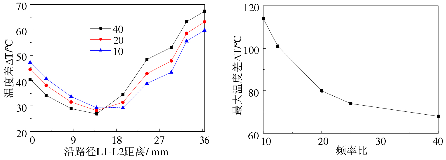
d) Maximum temperature difference curve of path L1-L2
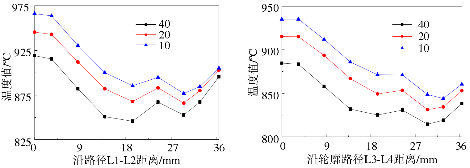
Comparing Fig. 1a), it can be found that by changing the current frequency ratio and current density ratio, the temperature trend in the tooth profile direction is basically the same, the tooth top temperature is higher, and the tooth surface temperature is still lower, which is related to the large curvature of the bevel gear tooth surface. However, along the direction of tooth profile, the temperature of tooth top is significantly higher than that of tooth surface and tooth root. When the current frequency ratio increases by 2 times, the temperature rise at the tooth top is significantly greater than that at the tooth root. It can also be seen from Fig. 1b) that the temperature at the 2.5mm depth of the tooth root changes little with the current frequency ratio, which is still related to the different structure of the tooth top and the tooth top, indicating that the heat generation rate and heat conduction rate of the bevel gear tooth root induction heating reach a dynamic balance.
It can be seen from figure 1c) that the temperature difference at the tooth root is greater than that at the tooth top. This is because the tooth root is close to the bevel gear matrix, the heat conduction effect of the tooth root is obvious, the strength of the tooth top, and the temperature gradient of the tooth root is large. According to the heat conduction formula in Chapter 2, the greater the temperature gradient, the stronger the heat conduction effect. With the increase of the current frequency ratio, the temperature difference between paths L1-L2 and L3-L4 changes little, because the tooth profile temperature exceeds the Curie temperature. At this time, the magnetic permeability of the tooth profile material is very small, resulting in the low heat generation efficiency of induction heating.
It can be seen from Fig. 1d) that when the high and intermediate frequency frequency ratio increases, the maximum temperature difference in the tooth profile direction decreases, which is mainly due to the reduction of the intermediate frequency frequency, resulting in the reduction of the tooth top temperature. However, it can be seen from Fig. 1a) that when the high and intermediate frequency frequency ratio increases, the temperature in the middle of the tooth surface also decreases, which will affect the austenite temperature layer depth of the tooth surface. Three paths: a-a1, b-b1 and c-c1 are selected to analyze the temperature field distribution in the tooth width direction of bevel gear.
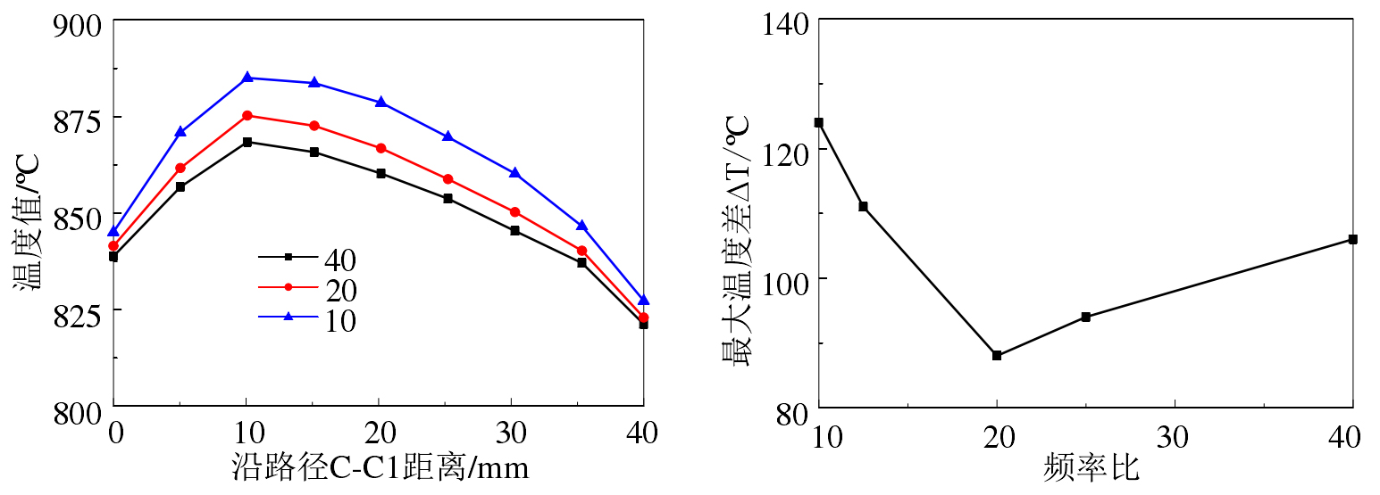
d) Maximum temperature difference curve of three paths in tooth width direction
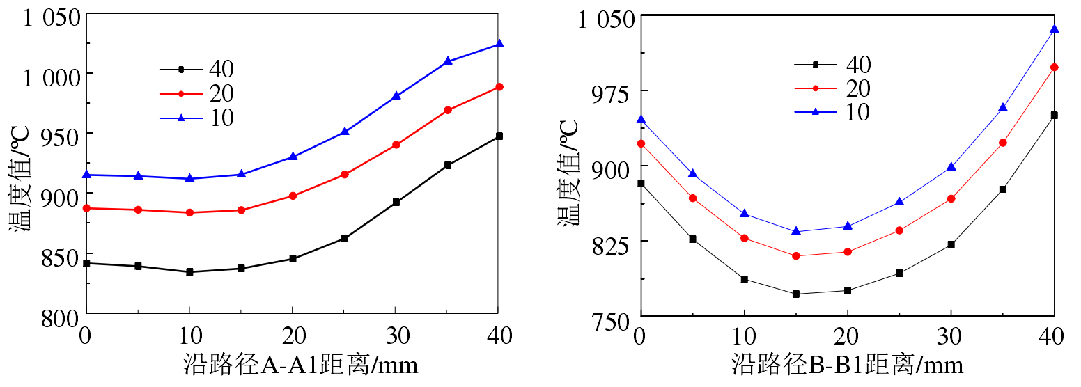
As can be seen from Figure 2, the temperature distribution is basically the same when changing the frequency ratio and current density ratio from the direction of bevel gear tooth width. Moreover, it can be seen that in the direction of bevel gear tooth width, the change of frequency ratio will not cause the sudden change of temperature distribution. From Fig. 2c), it can also be seen that the change of tooth root temperature value of high and intermediate frequency frequency frequency ratio has little effect. As can be seen from Fig. 2a), the temperature change of the tooth top decreases slightly every 2 times of the high and intermediate frequency frequency ratio. In the tooth width direction, due to the bevel gear structure, the temperature at the small end is significantly higher than that at the large end. Therefore, this should be fully considered when designing the sensor structure or setting parameters to avoid excessive temperature difference in the tooth width direction.
It can be seen from Fig. 2b) that the phenomenon of tooth top also exists at the tooth surface position, and the change of temperature value in the tooth width direction of bevel gear decreases slightly with the increase of frequency ratio. It is obvious from the curve that the temperature in the middle of the tooth surface is lower than that at both ends, which is caused by the sharp angle effect at the end. During induction heating, the austenitizing depth of the middle part can be improved by extending the induction heating time and allowing the temperature and heat at the tooth end to be transmitted to the middle part.
It can be seen from Fig. 2c) that at the tooth root, the change of frequency ratio is 2.5 times, the change of temperature value is small, and the maximum change is 14 º C. Therefore, it is impossible to increase the tooth root temperature by changing the high and intermediate frequency frequency frequency ratio, but the current density ratio can be increased. It can be seen that the tooth root temperature changes significantly by increasing the current density ratio.
As can be seen from Fig. 2d), when the high and intermediate frequency frequency ratio is 20, the temperature difference in the tooth width direction of the bevel gear is the smallest. When the frequency ratio decreases, the change of intermediate frequency frequency is large, and the difference of eddy flow caused by high and intermediate frequency current induction is large, resulting in a large temperature difference in the tooth width direction of bevel gear. When the frequency ratio increases, the change of intermediate frequency frequency is relatively small, and the intermediate frequency induction heating is low, so the change of temperature difference is small.