
First, create the process model of cutting tool machining gear, as shown in the figure. Therefore, we create the following theoretical model of gear hobbing machining. The hob makes the translational motion of cutting along the V direction in the translational coordinate system S1, AB and AC are the two sides of the gear hobbing tool, and the coordinate system S1 makes the translational motion to the right; The gear workpiece is fixed to the rotatable coordinate system S2, O2 is the center of the base circle of the gear, and the radius is ρ , The coordinate system SF is an auxiliary coordinate system and is fixed. The gear workpiece meshes with the hob clockwise, θ Is the rotation angle. Point O is the production point. In the meshing movement, it will move along the X1 axis. The two dashed lines on the left and right of AB segment are the two lines of tool profile error. Thirdly, we will simulate the machining process to analyze the mapping relationship between tool error and hobbing accuracy.

① Firstly, the gear involute equation is derived, which can be obtained from the coordinate transformation of the forming point:

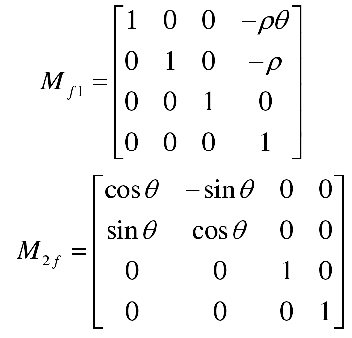
MF1 is the conversion matrix from coordinate system S1 to coordinate system SF;
M2F is the conversion matrix from the coordinate system SF to the coordinate system S2.
Coordinates in occurrence point S1:

According to the above data, the gear involute equation is obtained:

② The influence of tooth profile error on gear geometric accuracy is discussed
It can be seen from the above figure that the tooth profile of the hob is between the two limit error tooth profiles, and the specific shape is uncertain. In the analysis, we use these two limit tooth profiles as the maximum working size and minimum working size of the hob processing respectively, so as to determine the influence of the tool error on the gear accuracy.
Let the tooth profile deviation on the gear end face be Δ 。 In case of limit working size, the coordinates of the tool’s production point in S1 coordinate system:

According to the coordinate transformation matrix M2F MF1, the involute equation with error can be obtained:

According to the above analysis:
