
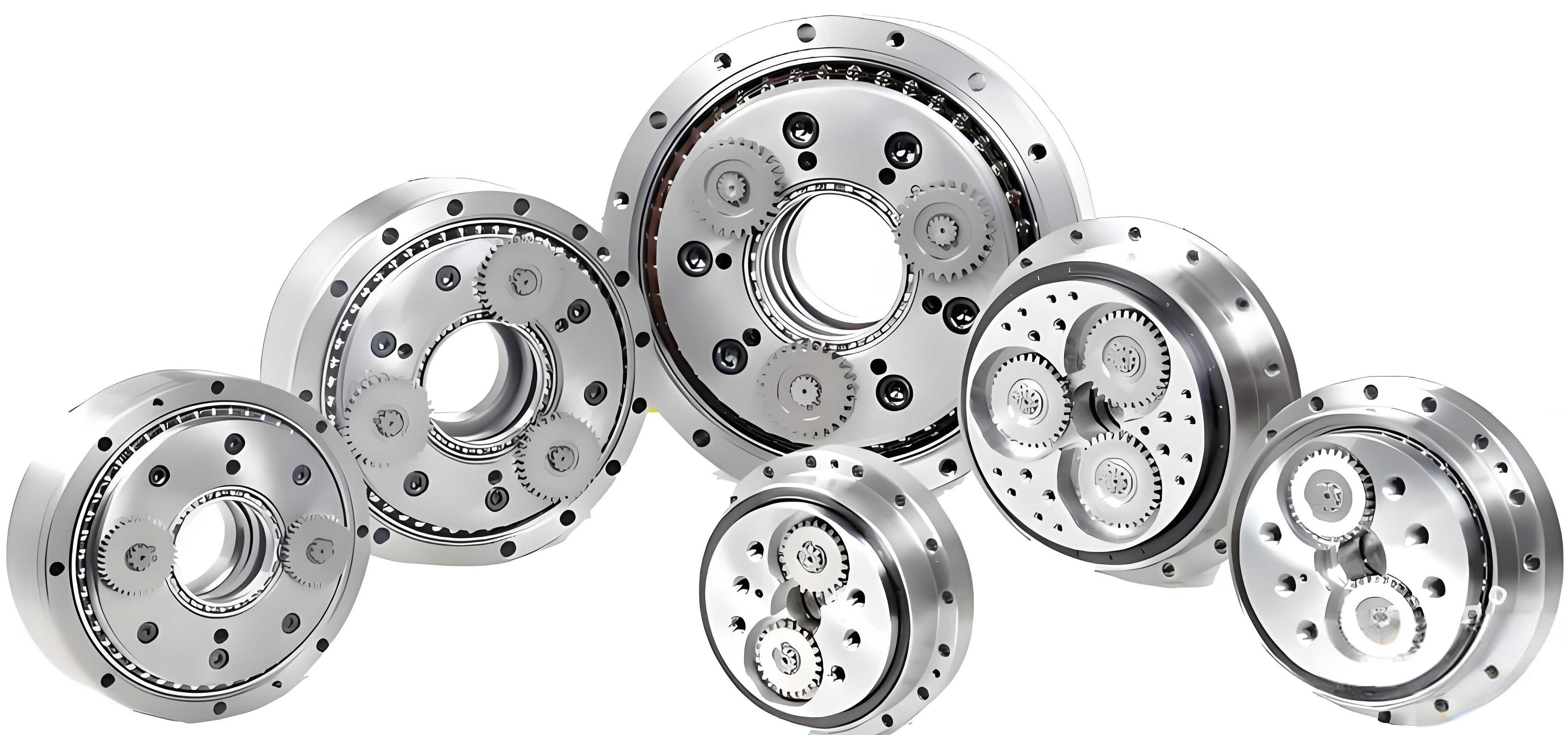
The progressive advancement of industrial automation has firmly established robotics technology as a cornerstone of modern manufacturing. Within this domain, the rotary vector reducer, serving as the critical actuation component in robotic joints, plays a decisive role in determining the operational precision, load capacity, and longevity of the entire system. The exceptional performance of the rotary vector reducer, characterized by high reduction ratios, compact size, high rigidity, and outstanding positional accuracy, is largely attributed to its unique two-stage transmission mechanism. The primary stage typically consists of a planetary gear train, while the crucial secondary stage employs a cycloid-pin gear mechanism, which is the heart of its high-performance transmission.
However, the high input speeds and significant torque multiplication inherent to the rotary vector reducer inevitably lead to the generation of substantial frictional heat at the meshing interfaces, particularly within the cycloid-pin gear stage. This thermal energy, if not properly managed, can induce detrimental effects such as thermal expansion, degradation of lubricant properties, accelerated wear, and in severe cases, thermal scuffing or seizure. These thermal issues ultimately compromise transmission accuracy, efficiency, and reliability. Therefore, conducting a thorough thermal analysis of the rotary vector reducer is of paramount theoretical and practical engineering significance. The cycloidal gear, as the core moving component in this frictional pair, is the primary source and carrier of this heat. Consequently, analyzing the temperature field of the cycloidal gear is essential for enhancing the overall thermal performance and lifespan of the rotary vector reducer.
In practical manufacturing and assembly, the theoretical conjugate meshing of a perfect cycloidal profile with pin gears is seldom employed. To compensate for manufacturing and assembly errors, facilitate assembly/disassembly, improve lubrication conditions, and optimize load distribution among teeth, deliberate modifications to the theoretical cycloidal tooth profile are universally applied. This process, known as profile modification, intentionally introduces a controlled amount of clearance between the cycloid tooth and the pin gear in the unloaded state. While the influences of various modification methods on mechanical performance metrics like transmission error, backlash, and contact stress have been studied extensively, their specific impact on the thermal behavior and steady-state temperature field of the gear remains a less explored yet critically important area. This paper aims to bridge this gap by systematically investigating the influence of different tooth profile modification schemes on the temperature characteristics of the cycloidal gear within a rotary vector reducer.
Fundamentals of Cycloid-Pin Gear Meshing in Rotary Vector Reducers
The kinematics and geometry of the cycloid-pin gear drive are well-established. The standard tooth profile of a cycloidal gear is generated by a rolling circle of radius \( r_r \) (where \( r_r = a \), the eccentricity) on the inside of a fixed base circle of radius \( R_p \) (the pin center circle radius). The parametric equations for the theoretical tooth profile are given by:
$$
\begin{aligned}
x &= (R_p – r_r \cos\theta) \cos\left(\frac{z_p}{z_c}\theta\right) + r_r \sin\theta \sin\left(\frac{z_p}{z_c}\theta\right) \\
y &= (R_p – r_r \cos\theta) \sin\left(\frac{z_p}{z_c}\theta\right) – r_r \sin\theta \cos\left(\frac{z_p}{z_c}\theta\right)
\end{aligned}
$$
where \( z_p \) is the number of pin gears, \( z_c \) is the number of cycloid gear teeth (typically \( z_c = z_p – 1 \)), and \( \theta \) is the rolling angle parameter. For a standard rotary vector reducer, the pins are fixed in the housing. When the input eccentric shaft rotates with an angular velocity \( \omega_H \), it imparts a composite motion to the cycloidal gear: a revolution around the central axis and a slower rotation about its own axis in the opposite direction. The reduction ratio \( i \) of the cycloid stage is \( i = z_c \).
The instantaneous contact between a cycloid tooth and a pin can be modeled, to a first approximation, as the contact between two cylinders. The radius of the pin is \( r_{rp} \). The radius of curvature of the cycloid tooth at the contact point, derived from differential geometry, is:
$$
\rho_i = \frac{(1 + K_1^2 – 2K_1 \cos \phi_i)^{3/2} R_p}{K_1(1 + z_p) \cos \phi_i – (1 + z_p K_1^2)} + r_{rp}
$$
where \( K_1 = a z_p / R_p \) is the shortening coefficient, and \( \phi_i \) is the meshing phase angle for the i-th tooth pair, measured from the line of centers. The equivalent radius of curvature \( \rho_{e,i} \) for the contact pair is then:
$$
\frac{1}{\rho_{e,i}} = \frac{1}{r_{rp}} – \frac{1}{\rho_i}
$$
Under load, the contact pressure distribution follows Hertzian theory. The maximum contact stress \( \sigma_{Hmax} \) and the semi-contact width \( a_H \) for a pair of elastic cylinders in line contact are given by:
$$
\sigma_{Hmax} = \sqrt{ \frac{F_i E^*}{\pi \rho_{e,i} b} }, \quad a_H = \sqrt{ \frac{4 F_i \rho_{e,i}}{\pi b E^*} }
$$
where \( F_i \) is the normal contact load on the i-th tooth pair, \( b \) is the face width of the gear, and \( E^* \) is the equivalent Young’s modulus, defined as \( \frac{2}{E^*} = \frac{1-\nu_1^2}{E_1} + \frac{1-\nu_2^2}{E_2} \). For gears and pins commonly made of bearing steel like GCr15, \( E_1 = E_2 = 206 \) GPa and \( \nu_1 = \nu_2 = 0.3 \).
Theory and Implementation of Tooth Profile Modification
Profile modification for cycloidal gears in rotary vector reducers primarily involves two fundamental types: equidistant modification and shifting modification, often used in combination.
- Equidistant Modification: This method involves generating the tooth profile using a rolling circle of radius \( r_r’ = r_r \pm \Delta r_r \), effectively offsetting the entire profile by a constant amount \( \Delta r_r \) relative to the pins. A positive equidistant modification (+Δr_r) increases the radius of the rolling circle, creating a larger “gap” or clearance between the tooth flank and the pin.
- Shifting Modification: This method involves generating the tooth profile relative to a pin center circle of radius \( R_p’ = R_p \pm \Delta R_p \). A positive shifting modification (+ΔR_p) effectively moves the pins radially outward relative to the gear center, again creating clearance.
In industrial practice, combined modification (both equidistant and shifting) is standard to achieve an optimal compromise between load capacity, lubrication, and manufacturing tolerance absorption. Given a target total radial clearance \( \Delta \), there are typically three viable combination schemes, as a negative-negative combination does not yield a practical profile. The initial meshing clearance \( \Delta \phi_i \) for a tooth at phase angle \( \phi_i \) under a combined modification is expressed as:
$$
\Delta \phi_i = \Delta r_r \left(1 – \frac{\sin \phi_i}{\sqrt{1+K_1^2-2K_1\cos\phi_i}}\right) + \frac{\Delta R_p}{R_p} \left(1 – K_1\cos\phi_i – \frac{\sqrt{1-K_1^2}\sin\phi_i}{\sqrt{1+K_1^2-2K_1\cos\phi_i}}\right)
$$
The objective is to determine the modification amounts \( \Delta r_r \) and \( \Delta R_p \) that yield a desired and controlled clearance \( \Delta \) while maintaining favorable load distribution. For the analysis in this work, a target radial clearance of \( \Delta = 6 \mu m \) was specified for a representative rotary vector reducer model. The optimized modification amounts for the three common combination types are presented in the table below.
| Modification Scheme | Equidistant Modification Δr_r (mm) | Shifting Modification ΔR_p (mm) |
|---|---|---|
| Positive Equidistant + Negative Shifting | +0.0158 | -0.0098 |
| Negative Equidistant + Positive Shifting | -0.0098 | +0.0158 |
| Positive Equidistant + Positive Shifting | +0.0158 | +0.0098 |
The primary mechanical consequence of profile modification is the alteration of the load-sharing behavior. For a perfect, unmodified (theoretical) profile under load, approximately half of the teeth are in simultaneous contact, sharing the load. With modification, under no load, only one or a few teeth are initially in contact. As torque is applied, the system components deform until a sufficient number of teeth come into contact to carry the load. This fundamentally changes the calculation of the load \( F_i \) on each individual tooth pair from a simple trigonometric distribution to a deformation compatibility problem.
Analytical Model for Frictional Heat Generation
The primary source of heat in a rotary vector reducer during operation is the friction at the sliding-rolling interfaces of the meshing cycloid teeth and pin gears. The instantaneous frictional heat flux generated at the contact interface of the i-th tooth pair is given by:
$$
Q_i = \sigma_{H,i} \, v_{r,i} \, f_i \, \gamma
$$
where:
- \( \sigma_{H,i} \) is the contact stress (approximated here as the average Hertzian stress, \( \sigma_{H,i} = (\pi/4) \sigma_{Hmax,i} \)).
- \( v_{r,i} \) is the relative sliding velocity between the cycloid tooth and the pin.
- \( f_i \) is the instantaneous coefficient of friction at the contact.
- \( \gamma \) is the energy conversion factor (typically 0.9–0.95), representing the fraction of frictional work converted into heat absorbed by the contacting bodies; the remainder is dissipated through other means like noise and vibration. We assume \( \gamma = 0.95 \).
Load and Stress Distribution for Modified Profiles
For modified profiles, the load on each tooth \( F_i \) must satisfy equilibrium and compatibility conditions. The total output torque \( T_c \) on a single cycloidal disk (considering two disks in a standard rotary vector reducer, \( T_c \approx 0.55T_{out} \)) is balanced by the sum of moments from all contacting teeth:
$$
T_c = \sum_{i=m}^{n} F_i \, l_i, \quad \text{where} \quad l_i = r_c \frac{\sin \phi_i}{\sqrt{1+K_1^2-2K_1\cos\phi_i}}
$$
Here, \( r_c = a z_c \) is the pitch radius of the cycloidal gear, and the summation runs from the first contacting tooth \( m \) to the last \( n \). The deformation compatibility condition states that the total deformation \( \delta_i \) (contact deformation + structural deflection) at any contacting tooth must equal its initial clearance \( \Delta \phi_i \) plus a base deformation. A common assumption is that the total deformation is proportional to the trigonometric term, i.e., \( \delta_i = (\sin\phi_i / \sqrt{s}) \delta_{max} \), where \( \delta_{max} \) is the deformation at the tooth experiencing maximum load \( F_{max} \). The load on any tooth is then related to the maximum load by:
$$
F_i = \frac{\delta_i – \Delta \phi_i}{\delta_{max}} F_{max} = \left( \frac{\sin \phi_i}{\sqrt{s} \delta_{max}} – \frac{\Delta \phi_i}{\delta_{max}} \right) F_{max}
$$
where \( s = 1+K_1^2-2K_1\cos\phi_i \). The term \( \delta_{max} \) itself depends on \( F_{max} \) through the Hertzian contact deformation formula \( w_{max} \) (other deflections like pin bending are often negligible in comparison for rigid pins):
$$
\delta_{max} \approx w_{max} = \frac{2(1-\nu^2)}{\pi E} \frac{F_{max}}{b} \left( \frac{2}{3} + \ln{\frac{4\rho_{e,max}}{c^2}} \right)
$$
Here, \( c \) is the half-width of the contact ellipse from the Hertzian solution. Solving for \( F_{max} \) and the individual \( F_i \) requires an iterative numerical procedure, starting from an initial guess \( F_{max0} = 2.2T_c / (K_1 z_c R_p) \). The results for contact stress \( \sigma_{H,i} \) for the standard and the three modified profiles are calculated and compared. A key finding is that modification reduces the number of simultaneously loaded teeth, thereby increasing the load and stress on the teeth that are in contact. The peak stress value also shifts towards the entry region of the meshing zone as the effective contact range decreases.
Sliding Velocity and Friction Coefficient
The relative sliding velocity \( v_{r,i} \) for a fixed pin and a rotating cycloidal gear is derived from the kinematics of the mechanism:
$$
v_{r,i} = \left( R_p \sqrt{s} – r_{rp} \right) \frac{\omega_H}{z_c}
$$
where \( \omega_H = 2\pi n_H / 60 \) is the input angular speed of the rotary vector reducer.
The coefficient of friction \( f_i \) is highly dependent on operating conditions, lubricant properties, and surface roughness. A widely used empirical formula for gear contacts is applied:
$$
f_i = 0.002 \left( \frac{F_{t,i}}{0.001 b} \right)^{0.2} \left( \frac{2 \eta_0 v_{n,i}}{0.001 \rho_{e,i}} \right)^{-0.05 x}
$$
where:
- \( F_{t,i} \) is the tangential force component.
- \( \eta_0 \) is the dynamic viscosity of the lubricant at operating temperature.
- \( v_{n,i} \) is the entrainment or rolling velocity.
- \( x \) is a roughness factor: \( x = 21.4 ( (S_{a1}+S_{a2})/(2d) )^{0.25} \), with \( S_a \) being the surface roughness and \( d \) the pitch diameter.
Integrating these components, the instantaneous frictional heat flux \( Q_i \) can be calculated along the path of contact. A significant observation is that the peak value of the instantaneous heat flux remains largely unchanged by profile modification for a given torque and speed. However, the location of this peak shifts along the tooth profile, moving closer to the tooth root (lower \( \phi_i \)) as the load-bearing zone becomes more concentrated.
Periodic Heat Flux for Steady-State Analysis
To compute the steady-state temperature field of the cycloidal gear, the transient, moving heat source must be converted into a time-averaged, periodic heat flux applied to the tooth surface. The heat generated at a point on the tooth surface is only present while the tooth is in the contact zone, which lasts for a time \( \Delta t_i = 2a_H / v_{r,i} \). The meshing period for a single tooth, the time between successive engagements, is \( T = 2\pi (z_p-1)/(z_p \omega_H) \). Therefore, the time-averaged, periodic heat flux \( q_i \) applied to the tooth surface region corresponding to contact point \( i \) is:
$$
q_i = \frac{\Delta t_i}{T} Q_i = \frac{2 a_H / v_{r,i}}{T} Q_i
$$
This periodic heat flux \( q_i \) is the primary thermal boundary condition used in the finite element model to simulate the steady-state temperature. Calculations show that the values of \( q_i \) increase significantly for modified profiles because the contact load \( F_i \) (and thus \( a_H \) and \( Q_i \)) is higher on the fewer contacting teeth. The distribution of \( q_i \) along the tooth height is also altered.
| Parameter | Symbol | Value | Unit |
|---|---|---|---|
| Output Torque | \( T_{out} \) | 784 | N·m |
| Output Speed | \( n_{out} \) | 15 | rpm |
| Cycloid Gear Face Width | \( b \) | 16 | mm |
| Number of Cycloid Teeth | \( z_c \) | 39 | – |
| Number of Pin Gears | \( z_p \) | 40 | – |
| Eccentricity | \( a \) | 1.5 | mm |
| Pin Radius | \( r_{rp} \) | 3.0 | mm |
| Pin Center Circle Radius | \( R_p \) | 76.5 | mm |
| Young’s Modulus (GCr15 Steel) | \( E \) | 2.06×10⁵ | MPa |
| Poisson’s Ratio | \( \nu \) | 0.3 | – |
| Lubricant Dynamic Viscosity | \( \eta_0 \) | 0.05 | Pa·s |
| Ambient Temperature | \( T_{amb} \) | 22 | °C |
Finite Element Modeling for Steady-State Temperature Field
The steady-state temperature field of the cycloidal gear is obtained by solving the heat conduction equation with the appropriate boundary conditions. The governing equation is:
$$
\nabla \cdot (k \nabla T) + \dot{q}_{gen} = 0
$$
where \( k \) is the thermal conductivity of the material (44 W/(m·°C) for GCr15 steel), and \( \dot{q}_{gen} \) is the internal heat generation rate per unit volume (zero in this case, as heat is generated at the surface). The boundary conditions are:
- Heat Flux Boundary: The periodic heat flux \( q_i \) calculated above is applied to the active tooth flank surfaces corresponding to the meshing zone.
- Convective Boundary: All exposed surfaces of the cycloidal gear lose heat to the surrounding lubricant and air via convection. The convection heat transfer coefficient \( h \) varies depending on the surface geometry and local velocity.
- For tooth flanks and other surfaces with significant relative oil flow, an empirical correlation for forced convection over a flat plate is used: \( h_c = 0.664 k_{oil} (Re)^{1/2} (Pr)^{1/3} / L \), where \( Re \) is Reynolds number, \( Pr \) is Prandtl number, and \( L \) is characteristic length.
- For end faces rotating in oil, a correlation for a rotating disk can be applied: \( h_d = 0.616 k_{oil} (Re_\omega)^{1/2} (Pr)^{1/2} / r \), where \( Re_\omega \) is the rotational Reynolds number.
For simplification in this analysis, an effective average convection coefficient is estimated for different regions of the gear.
- Temperature Boundary: The inner bore of the cycloidal gear, which is mounted on the output flange or bearings, is often assumed to be at a stabilized bulk temperature. A reasonable assumption is a constant temperature slightly above ambient, or a convective boundary with a high coefficient representing good conductive coupling.
A three-dimensional finite element model of one tooth sector of the cycloidal gear, incorporating cyclic symmetry, is constructed. The applied periodic heat flux is mapped onto the tooth surface based on the meshing phase angle. The model is solved iteratively until convergence to a steady-state solution is achieved.
Results and Comparative Analysis
The steady-state temperature fields for the standard (unmodified) profile and the three modified profiles were computed. The results reveal critical insights into the thermal behavior of the rotary vector reducer‘s cycloidal gear.
Standard Profile: The temperature distribution for the standard profile shows a relatively broad heated region across the flank of the tooth, corresponding to the wider load-bearing zone. Heat conducts symmetrically along the face width from the central region of highest heat flux. The maximum steady-state temperature for the standard profile under the given operating conditions was found to be approximately 41.7°C.
Modified Profiles: All three modification schemes resulted in a reduction of the gear’s maximum steady-state temperature compared to the standard profile. This is a significant finding, indicating that proper profile modification not only improves mechanical performance but also has a beneficial thermal effect. The reduction occurs because, while the instantaneous heat flux per contacting tooth may be higher, the total frictional power loss might be slightly optimized, and more importantly, the concentration of heat input into a smaller surface area allows for more efficient lateral conduction and convective dissipation from that localized hot spot, preventing the heat from spreading as deeply into the gear body before being carried away.
The effectiveness of temperature reduction, however, varies among the three modification types:
- Positive Equidistant + Negative Shifting: This combination provided a moderate reduction in maximum temperature.
- Negative Equidistant + Positive Shifting: This scheme yielded a more pronounced temperature reduction than the first.
- Positive Equidistant + Positive Shifting: This combination proved to be the most effective in lowering the steady-state operating temperature of the cycloidal gear among the three studied.
The reason for the superior performance of the Positive-Positive modification can be linked to its initial clearance function \( \Delta \phi_i \). This scheme typically creates a larger initial clearance near the pitch point and a more favorable distribution of clearance along the flank, which may lead to a more optimal elastohydrodynamic lubrication film and slightly different load distribution, ultimately resulting in lower frictional losses and better heat dissipation characteristics.
Another distinct observation is the change in the temperature gradient on a single tooth. For the modified profiles, the region of highest temperature is more localized and concentrated around the new, smaller effective contact zone. Consequently, the temperature gradients (the rate of temperature change per unit distance) within this localized region are much steeper or denser than those observed in the standard profile. The density of these isotherms increases as the load-bearing contact range decreases. This implies that modified teeth experience a very hot, highly localized region flanked by significantly cooler material, which could have implications for thermal stress development.
| Profile Type | Approx. Meshing Zone (Δφ) | Peak Periodic Heat Flux \( q_{max} \) (W/m²) | Max. Steady-State Temp. (°C) | Temp. Reduction vs. Standard | Temp. Gradient Concentration |
|---|---|---|---|---|---|
| Standard (Unmodified) | Wide (~180° sym) | q_s | 41.7 | Baseline | Moderate, spread |
| Pos. Eq. + Neg. Sh. | Reduced | > q_s | ~40.1 | ~1.6°C | High, localized |
| Neg. Eq. + Pos. Sh. | Reduced | > q_s | ~39.4 | ~2.3°C | High, localized |
| Pos. Eq. + Pos. Sh. | Reduced | > q_s | ~38.8 | ~2.9°C | Highest, most localized |
Discussion and Implications for Rotary Vector Reducer Design
The analysis confirms that tooth profile modification in cycloidal gears is a critical design aspect that influences not only mechanical metrics like stress, accuracy, and backlash but also the thermal state of the rotary vector reducer. The key thermal findings can be summarized as follows:
- Temperature Reduction: All practical combination modification schemes lead to a lower steady-state operating temperature for the cycloidal gear compared to the theoretical profile. This is beneficial for overall system reliability, lubricant life, and mitigating thermal distortion.
- Optimal Modification for Cooling: For the specific case studied with a radial clearance of 6 μm, the positive equidistant combined with positive shifting modification yielded the most significant temperature reduction. This suggests that this modification type promotes the most favorable combination of load distribution and lubrication for minimal thermal energy generation and/or optimal heat dissipation.
- Heat Flux Characteristics: The instantaneous frictional heat flux peak is not significantly amplified by modification; rather, its location shifts. In contrast, the periodic heat flux used for steady-state analysis does increase in magnitude on the loaded teeth due to the higher individual loads. Its peak consistently occurs at a similar meshing phase angle (dictated by the maximum of the \( \sin\phi/\sqrt{s} \) term in the load distribution), but the absolute value scales with the increased contact pressure.
- Thermal Gradient Localization: Modification concentrates the frictional heat input into a smaller area of the tooth flank. This results in a more localized high-temperature region surrounded by steeper thermal gradients. Designers must consider the potential for higher localized thermal stresses, which could influence fatigue life, even though the bulk temperature is lower.
These insights provide valuable guidance for the integrated thermo-mechanical design of high-performance rotary vector reducers. Future work could extend this analysis by coupling the thermal model with a thermo-elastohydrodynamic lubrication (TEHL) model to more accurately predict the friction coefficient and film thickness under modified profiles. Furthermore, a transient thermal analysis considering duty cycles and a full system-level thermal model of the rotary vector reducer, including housing and bearings, would provide a complete picture of the thermal management requirements for advanced robotic applications.