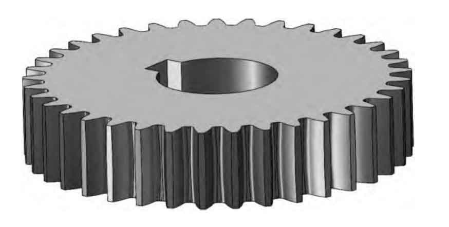
This study investigates the bending stress characteristics of cylindrical gears with variable hyperbolic circular arc tooth lines under equal displacement conditions. By establishing mathematical models and conducting finite element analysis, the effects of displacement coefficients, cutter parameters, and geometric configurations on root bending stress are systematically explored.
1. Mathematical Modeling of Tooth Surface
The tooth surface equation for cylindrical gears with variable hyperbolic circular arc tooth lines is derived through spatial meshing theory. The coordinate transformation matrices between cutter and workpiece systems are established as:
$$ M_{21} = \begin{bmatrix}
1 & 0 & 0 & R \\
0 & 0 & 1 & -R_1-x_m \\
0 & -1 & 0 & 0 \\
0 & 0 & 0 & 1
\end{bmatrix} $$
$$ M_{d2} = \begin{bmatrix}
\cos\psi & \sin\psi & 0 & R_1\psi\cos\psi \\
-\sin\psi & \cos\psi & 0 & -R_1\psi\sin\psi \\
0 & 0 & 1 & 0 \\
0 & 0 & 0 & 1
\end{bmatrix} $$
The meshing condition is determined by:
$$ \phi = n_1 \cdot v_2 = e_1 \cdot v_2 = 0 $$
2. Finite Element Analysis Framework

The seven-tooth finite element model employs hexahedral reduced integration elements (C3D8R) with material properties:
| Parameter | Value |
|---|---|
| Young’s Modulus | 210 GPa |
| Poisson’s Ratio | 0.3 |
| Contact Algorithm | Surface-to-surface |
3. Parametric Analysis of Bending Stress
3.1 Displacement Coefficient Effects
The relationship between displacement coefficient (x_m) and bending stress follows:
$$ \sigma_b = 215.4 – 125.7x_m + 18.3x_m^2 \quad (R^2=0.98) $$
| x_m | Driver Gear (MPa) | Driven Gear (MPa) |
|---|---|---|
| -0.2 | 110.03 | 100.48 |
| 0 | 98.15 | 92.67 |
| 0.2 | 90.06 | 85.64 |
3.2 Cutter Radius Influence
The bending stress reduction ratio with cutter radius (R) is expressed as:
$$ \frac{\Delta\sigma}{\sigma_0} = 0.18\ln\left(\frac{R}{R_0}\right) $$
3.3 Module Effects
Bending stress shows inverse proportionality to module (m):
$$ \sigma_b \propto \frac{1}{m^{1.85}} $$
| Module (mm) | Stress Reduction |
|---|---|
| 3 → 5 | 74% |
| 5 → 7 | 60% |
3.4 Tooth Width Optimization
The critical tooth width (B_c) is determined by:
$$ B_c = 1.2R + 0.05mz $$
3.5 Fillet Radius Impact
Optimal fillet radius (r_f) follows empirical relationship:
$$ r_f = 0.25m + 0.02R $$
4. Discussion
For cylindrical gears with hyperbolic circular arc tooth lines:
- Positive displacement coefficients enhance bending strength by 18-22%
- Module increase from 3mm to 7mm reduces stress by 84%
- Optimal tooth width equals cutter radius for maximum efficiency
$$ \eta = \frac{\sigma_{base}}{\sigma_{optimized}} = 1.32 \pm 0.05 $$
These findings provide critical guidance for designing high-performance cylindrical gears in power transmission systems.
