
The stiffness excitation and friction excitation change after helical gear modification. The coupling dynamic model of helical gear modification and friction excitation is used to study the influence of modification on the dynamic response characteristics of helical gear system. The dynamic response of helical gear system with friction coefficient of 0.1 before and after modification is simulated and calculated. The vibration displacement and vibration velocity of the driving wheel in X, y and Z directions are shown in Fig. 1, Fig. 2 and Fig. 3 respectively. The vibration displacement and vibration velocity of the driven wheel in X, y and Z directions are shown in Fig. 4, FIG. 5 and Fig. 6 respectively. Figure 1 (a) and Figure 4 (a) show that the vibration displacement amplitude of driving wheel and driven wheel in X direction decreases after modification, and the vibration amplitude also decreases after modification. Figure 1 (b) and Figure 4 (b) It shows that the vibration velocity amplitude of the driving wheel and driven wheel in the X direction after modification is lower than that before modification. Fig. 2, FIG. 5, Fig. 3 and Fig. 6 show that the vibration displacement and vibration velocity amplitude fluctuation range of the driving wheel and driven wheel in the Y and Z directions after modification are significantly reduced.

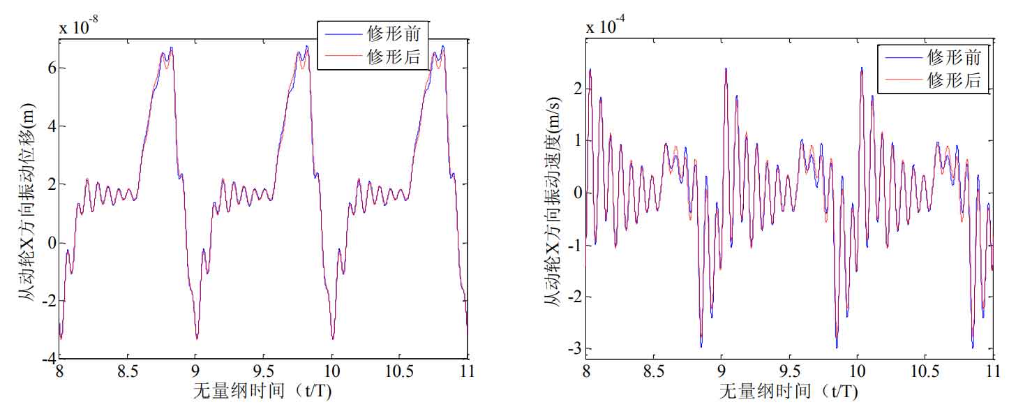


Figure 7 shows the dynamic meshing force and friction force of helical gear before and after modification. Figure 7 (a) shows that the fluctuation amplitude of dynamic meshing force of helical gear system decreases after modification. Figure 7 (b) shows the friction calculated by dynamic meshing force. It can be seen from the figure that the friction amplitude decreases and the fluctuation amplitude decreases after modification.

Figure 8 shows the dynamic transmission error curve of helical gear before and after modification. Figure 8 (a) shows that the fluctuation range of the dynamic transmission error curve of the modified helical gear system decreases. Figure 8 (b) shows the frequency domain diagram of the dynamic transmission error of the helical gear system before and after modification. After modification, the vibration displacement amplitude of each meshing order decreases. And figure 8 (a) The dynamic transmission error of the helical gear system shown in Fig. 9 is similar to the change trend of the static transmission error of the helical gear calculated by romax. The fluctuation range of the dynamic transmission error before modification is large, and the fluctuation range of the dynamic transmission error after modification is small, which verifies the correctness of the dynamic model.